Filtering face-piece respirator having an auxetic mesh in the mask body

a mask body and auxetic mesh technology, applied in the field of mask body auxetic mesh filtering facepiece respirator, can solve the problems of affecting the affecting the air quality of air inhalation,

Inactive Publication Date: 2015-03-03
3M INNOVATIVE PROPERTIES CO
View PDF97 Cites 9 Cited by
  • Summary
  • Abstract
  • Description
  • Claims
  • Application Information

AI Technical Summary

Benefits of technology

[0008]The present invention differs from known filtering face-piece respirators in that the mask body comprises a support structure that includes a molded auxetic mesh. Although polymeric meshes have been successfully used as support structures in mask bodies, the mesh structures that have been used have not been auxetic—that is, they do not exhibit a negative Poisson ratio. Meshes that exhibit a negative Poisson ratio can be stretched in at least one dimension, causing the mesh to expand in the transverse direction. The inventor discovered that an auxetic mesh will distort less when molded. The auxetic mesh provides more uniformity in the size of mesh openings in the resulting molded structure. Improvements in mesh opening uniformity can provide a mask body that has better aesthetics. Known respiratory masks—which have used non-auxetic open-work meshes as the support structure—have exhibited obvious variations in the size of the mesh openings. The different sized openings may be considered unsightly, and portions of the mesh may sometimes overlap and distort during the molding operation. The present invention alleviates such issues and accordingly provides a molded filtering face-piece respirator that may be considered to have an improved appearance. When making respirators of the present invention, there can be less opportunity for respirator waste—as there may be less mask bodies that are discarded due to such manufacturing defects.GLOSSARY

Problems solved by technology

Although polymeric meshes have been successfully used as support structures in mask bodies, the mesh structures that have been used have not been auxetic—that is, they do not exhibit a negative Poisson ratio.
The different sized openings may be considered unsightly, and portions of the mesh may sometimes overlap and distort during the molding operation.

Method used


Image

  • Filtering face-piece respirator having an auxetic mesh in the mask body
  • Filtering face-piece respirator having an auxetic mesh in the mask body
  • Filtering face-piece respirator having an auxetic mesh in the mask body

Examples


examples

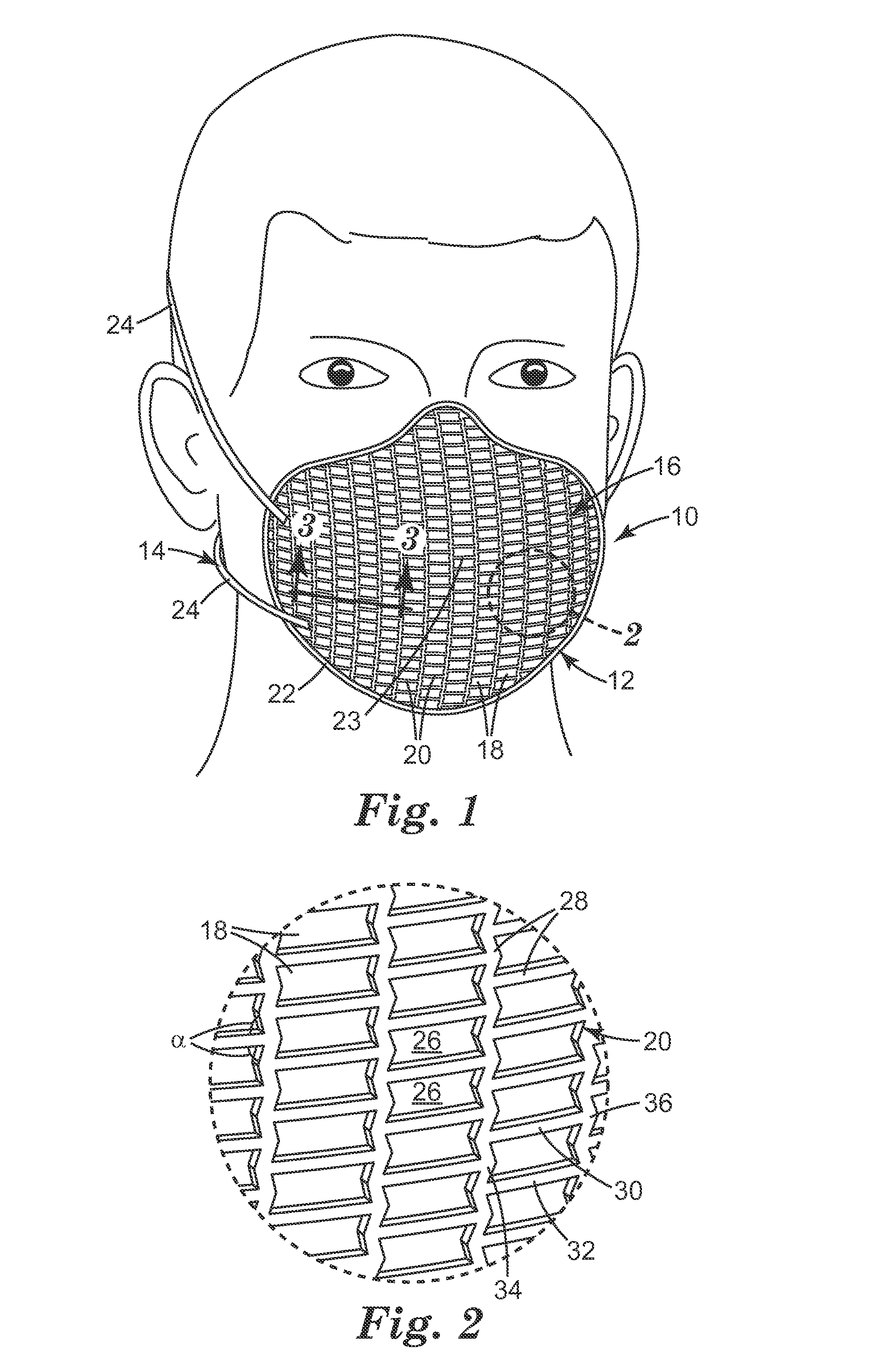
[0062]Cell Size Determination

[0063]Auxetic mesh cell size was determined using defined diameter rods that were mounted in a fixture to facilitate measurement of the open spaces or cells. The probe rods ranged in diameter from 0.0254 cm (centimeter) to 0.5334 cm, in 0.0254 cm increments. The cell size was measured by selecting the maximum size probe that fit into the cell without causing distortion of the cell shape prior to placement of the probe. This size was recorded, and the next cell size was measured and recorded until all cells contained within the molded mesh were measured and the cells tallied at each probe size.

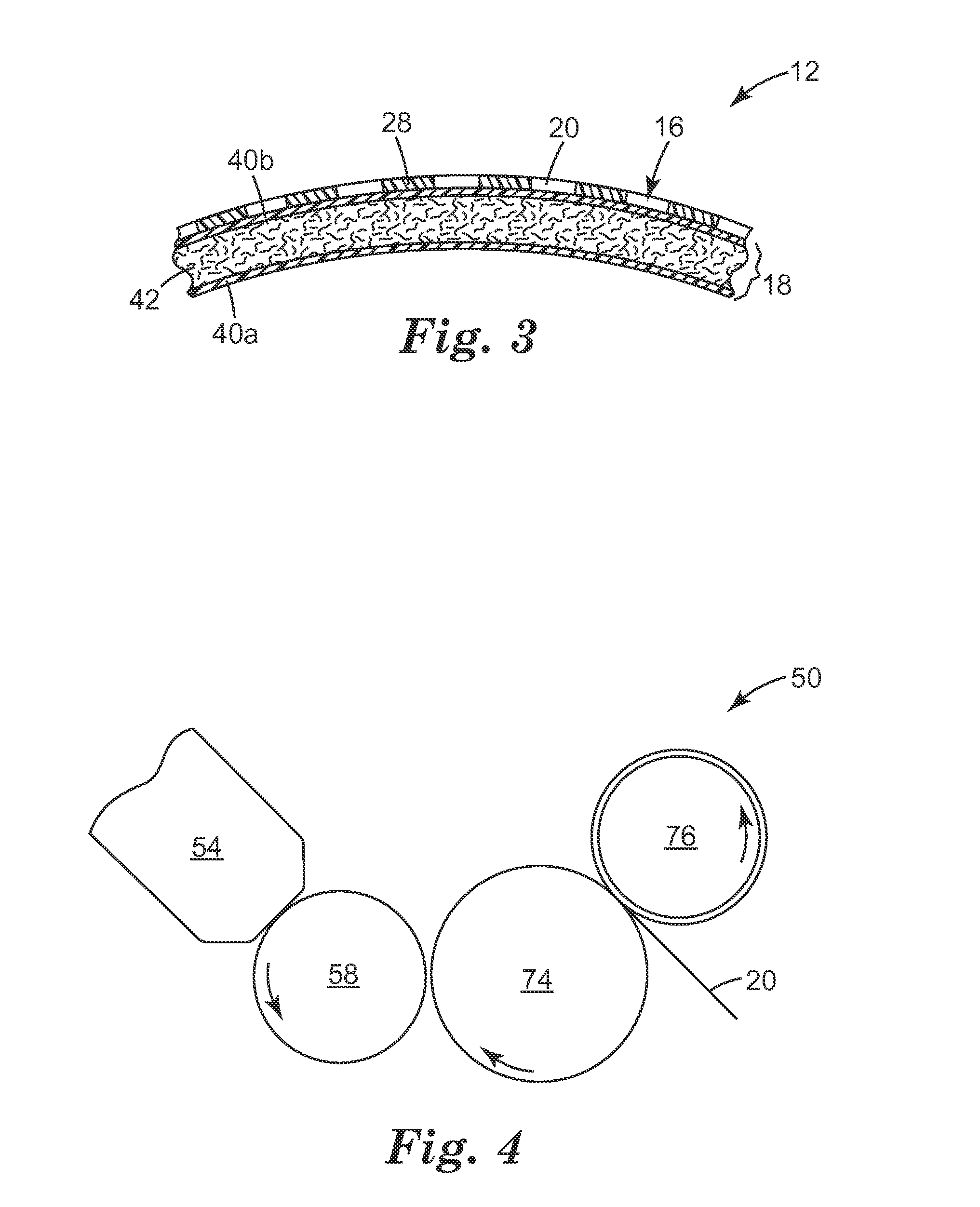
[0064]Auxetic Mesh Formation Apparatus and Process

[0065]An auxetic web was produced using a system 50 that resembles the apparatus shown in FIG. 4. A 40 mm diameter twin-screw extruder was fitted with a gear pump and was used to deliver a molten polymer blend at melt temperature of approximately 246° C. to a slot die 54, at an extrusion rate of 1.43 kg / hr / cm (kilogr...


PUM

PropertyMeasurementUnit
angleaaaaaaaaaa
angleaaaaaaaaaa
thicknessaaaaaaaaaa

Abstract

A filtering face-piece respirator 10 that has a harness 14 and a mask body 12. The mask body 12 includes a support structure 16 and a filtering structure 18. The support structure 16 contains an auxetic mesh 20 that has been molded into an intended cup-shape configuration, and the filtering structure 18 contains a filtration layer 42 for removing contaminants from the ambient air. The use of an auxetic mesh 20 in the support structure 16 provides more uniformly-sized openings 26 in the mesh 20 and reduces opportunities for mesh overlapping and mesh distortion.

Description

CROSS-REFERENCE TO RELATED APPLICATION[0001]This application claims the benefit of U.S. Provisional Patent Application No. 61 / 291,052, filed Dec. 30, 2009.[0002]The present invention pertains to a filtering face-piece respirator that has an auxetic mesh in the support structure of the mask body.BACKGROUND[0003]Respirators are commonly worn over the breathing passages of a person for at least one of two common purposes: (1) to prevent impurities or contaminants from entering the wearer's breathing track; and (2) to protect other persons or things from being exposed to pathogens and other contaminants exhaled by the wearer. In the first situation, the respirator is worn in an environment where the air contains particles that are harmful to the wearer, for example, in an auto body shop. In the second situation, the respirator is worn in an environment where there is risk of contamination to other persons or things, for example, in an operating room or clean room.[0004]A variety of resp...

Claims


Application Information

Patent Timeline
Patent Type & Authority Patents(United States)
IPC IPC(8): A62B7/10A41D13/11A62B18/02A62B23/02B29C39/14B29D28/00B29L28/00B29L31/14B29L31/48
CPCA62B18/025A62B23/025B29C39/148B29D28/00A41D13/1138A41D13/1146B29L2028/00B29L2031/14B29L2031/4835Y10T29/4998
Inventor MARTIN, PHILIP G.
Owner 3M INNOVATIVE PROPERTIES CO
Why Eureka
Try Eureka