Liquefier for a heat pump and heat pump

a heat pump and liquefier technology, applied in the field of heat pumps, can solve the problems of not reducing the overall efficiency of the heat pump, heat loss via the process water tank is especially disadvantageous, and the space for insulating materials is not large enough, so as to achieve the effect of better insulation

Active Publication Date: 2015-03-17
EFFICIENT ENERGY GMBH
View PDF24 Cites 1 Cited by
  • Summary
  • Abstract
  • Description
  • Claims
  • Application Information

AI Technical Summary

Benefits of technology

[0017]The present invention is based on the finding that the simplest, and at the same time most efficient accommodation of the process water tank is achieved in the working fluid space of the liquefier. The working fluid space and the process water tank are arranged so that the process water tank has a wall spaced from a wall of the working fluid space. Hence, a gap, which at least partially comprises neither working fluid in liquid form nor process water, but is only filled with vapor, is obtained between these two walls. This vapor may be the same compressed working vapor that is transported into the liquefier from the compressor. This compressed working vapor fills the gap between the process water tank and the working fluid space.
[0020]In an embodiment, the heat pump is operated with water. As compared with the atmospheric pressure, even compressed vapor, as is present in such a heat pump, has relatively low pressure, such as 100 mbar (100 hPa). Hence, the insulating effect between the process water tank and the liquefied working fluid is increased even more as compared with higher pressures of the vapor. This is due to the fact that the insulating effect of a gas-filled gap becomes greater, the smaller the pressure of the gas becomes, with the best insulating effect being achieved when there is a vacuum in the gap.
[0023]Furthermore, temperatures substantially higher than the liquefier temperatures are reached in the intermediate cooler due to the overheating properties, which additionally assists in maintaining hygienic conditions in the process water tank.
[0025]The arrangement of the process water tank in the liquefier, and particularly in the working fluid space of the liquefier, wherein the process water tank is, however, thermally separated from the working fluid space via a gap filled with gas or vapor, entails several advantages. One advantage is that the process water tank does not need any additional space, but is contained within the volume of the working fluid space. Hence, the heat pump does not have any additional complicated form and is compact. Moreover, the process water tank does not need insulation of its own. This insulation would be necessitated if it was attached at another place. However, the entire working fluid space, and particularly the gap filled with gas and / or vapor, now acts as an inherent insulation. Furthermore, heat losses, which may still occur, are uncritical because the entire heat given off by the process water tank reaches the liquefier itself, where it is often used as heating heat. Real losses are only heat losses to the outside, i.e. to the surrounding air, which do not occur in the process water tank, however.
[0026]It is further advantageous that the gas filling for the gap between the wall of the process water tank and the wall of the working fluid space does not have to be specially manufactured. Instead, the working vapor itself, which is present in the liquefier anyway, is used advantageously to this end. Apart from the fact that vapor and / or gas have a better insulation effect than the liquefied vapor, i.e. the water and / or the liquefied gas, the insulation between the process water tank and the working fluid space is especially good when the heat pump works with water as the working fluid, because the pressure in the liquefier, albeit higher than the pressure in the evaporator, is relatively low, such as at 100 hPa, which corresponds to medium negative pressure.
[0028]All these properties do not only lead to the fact that the heat pump as a whole becomes more compact and therefore more inexpensive and better to handle, but also to the fact that the losses of the heat pump are minimized further. All the heat losses from the process water actually are no real losses, because the heat only reaches the liquefier space and is beneficial there for heating the heating cycle. Nevertheless, however, it is easily possible, due to the good insulation, to maintain a higher temperature in the process water tank, at least in the upper region, than is present in the liquefied working fluid, because a higher temperature is generated in the intermediate cooler, which temperature is, for example, directly given off to the process water, i.e. without a heat exchanger therebetween, and is fed to the process water tank in the upper region, which is where the warmest layer of the process water tank is located.

Problems solved by technology

However, this does not reduce the overall efficiency of the heat pump, but even increases it, because two successively connected flow machines with gas cooling connected therebetween achieve the demanded gas pressure in the liquefier with a longer life due to the reduced thermal stress and with less energy than if a single flow machine without gas cooling were present.
At the same time, the process water tank should be sufficiently insulated, since heat loss via the process water tank is especially disadvantageous.
This means that the process water tank is to be insulated especially well, which again entails both space for insulating materials and costs of the insulating materials.
On the other hand, each step of later assembly of a heating system leads to costs for the workman and at the same time also to additional fault liability.
Moreover, the insulation material needed for insulating the process water tank also is expensive if good insulation effects are to be achieved.

Method used


Image

  • Liquefier for a heat pump and heat pump
  • Liquefier for a heat pump and heat pump
  • Liquefier for a heat pump and heat pump

Examples


Embodiment Construction

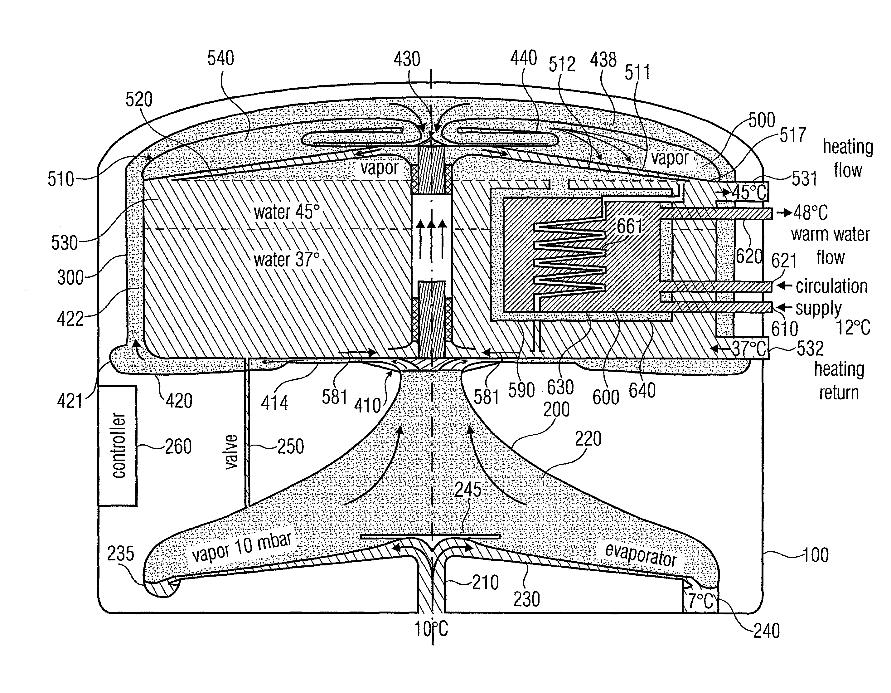
[0039]FIG. 1 shows a schematic cross-sectional view of a heat pump in which a liquefier may be employed advantageously. The heat pump includes a heat pump housing 100 comprising, in a setup direction of the heat pump from the bottom to the top, first an evaporator 200 and a liquefier 300 above it. Furthermore, a first compressor stage 410 feeding a first intermediate cooler 420 is arranged between the evaporator 200 and the liquefier 300. Compressed gas output from the intermediate cooler 420 enters a second compressor stage 430 and there is condensed and supplied to a second intermediate cooler 440, from which the compressed, but intermediately cooled gas (vapor) is fed to a liquefier 500. The liquefier has a liquefier space 510, which comprises a working fluid space filled with liquefied working fluid, such as water, up to a filling level 520. The liquefier 500 and / or the liquefier space 510 are limited to the outside by a liquefier wall 505, which provides a lateral boundary of t...


PUM

PropertyMeasurementUnit
angleaaaaaaaaaa
temperatureaaaaaaaaaa
pressureaaaaaaaaaa

Abstract

A liquefier for a heat pump includes a liquefier space and a process water tank. The process water tank is arranged within the liquefier space such that it is substantially surrounded by liquefied working fluid. A wall of the process water tank, however, is spaced from a wall of the process water tank so that a gap formed to communicate with the region of the heat pump in which compressed gas is present is obtained, so that the process water tank is thermally insulated from the space for liquefied working fluid via this gas-filled gap. The liquefier itself may also be surrounded by the gas region, in order to provide for inexpensive insulation of the liquefier.

Description

CROSS-REFERENCE TO RELATED APPLICATION[0001]This application is a U.S. National Phase entry of PCT / EP2009 / 002315 filed Mar. 30, 2009, and claims priority to German Patent Application No. 10 2008 016663.4.2 filed Apr. 1, 2008, each of which is incorporated herein by references hereto.BACKGROUND OF THE INVENTION[0002]The present invention relates to heat pumps, and particularly to heat pumps that may be employed for supplying a heating cycle and a process water cycle.[0003]WO 2007 / 118482 discloses a heat pump with an evaporator for evaporating water as the working liquid to produce working vapor. The heat pump further includes a compressor coupled to the evaporator to compress the working vapor. Here, the compressor is formed as a flow machine, wherein the flow machine comprises a radial wheel accepting uncompressed working vapor at its front side and expelling same by means of correspondingly formed blades at its side. By way of the suction, the working vapor is compressed so that co...

Claims


Application Information

Patent Timeline
Patent Type & Authority Patents(United States)
IPC IPC(8): F25B1/10F24D3/08F24D3/18F24D11/02F24D17/02F24J3/00F25B30/06F25B39/04
CPCF25B39/04F24D3/08F24D3/18F24D11/0214F24D17/02F24J3/00Y02B30/126F25B30/06F25B2339/047F25B2400/072F25B2500/01Y02B30/12F25B1/10Y10T29/49355Y10T29/49359F24V99/00Y02A40/963B23P15/26F25B30/02F25B39/02
Inventor SEDLAK, HOLGERKNIFFLER, OLIVER
Owner EFFICIENT ENERGY GMBH
Why Eureka
Try Eureka