Fabrication method of electrochromic element

a technology of electrochromic elements and fabrication methods, applied in the direction of chemistry apparatus and processes, instruments, lamination ancillary operations, etc., can solve the problems of requiring a higher driving voltage, fewer color-levels, poor color contrast, etc., and achieves a long-term memory effect, low driving voltage, and better color contrast

Active Publication Date: 2015-03-31
IND TECH RES INST
View PDF1 Cites 5 Cited by
  • Summary
  • Abstract
  • Description
  • Claims
  • Application Information

AI Technical Summary

Benefits of technology

[0006]An object of the present invention present is to provide a fabrication method of an electrochromic element. The light transmittance and appearance color of the electrochromic element can change according to various applied voltages, and infrared and harmful light can be isolated. Additionally, the electrochromic element of the present invention requires a lower driving voltage, performs with a better color contrast and a long-time memory effect.
[0027]The transmittance of the electrochromic element for visible light is about 15-70%, and the transmittance of the electrochromic element for infrared is lower than 3%. After a voltage is applied on the electrochromic element and then cut off, the color of the electrochromic element can maintain for 1-8 hours, so that infrared and harmful light can be isolated. Additionally, the electrochromic element of the present invention requires a lower driving voltage, performs with a better color contrast and a long-time color-changing memory effect.
[0028]The light transmittance and appearance color of the electrochromic element can change according to various applied voltages, and infrared and harmful light can be isolated. Additionally, the electrochromic element of the present invention requires a lower driving voltage, performs with a better color contrast and a long-time color-changing memory effect.

Problems solved by technology

However, the conventional electrochromic unit requires a higher driving voltage, performs with fewer color-levels and worse color contrast.
Besides, the electrochromic unit is generally applied to LCD, and thus requiring a higher driving voltage and being unable to maintain the appearance color.
Furthermore, the transmittance of the electrochromic device for infrared is considerably high, thus infrared and harmful light cannot be sufficiently isolated.

Method used


Image

  • Fabrication method of electrochromic element
  • Fabrication method of electrochromic element
  • Fabrication method of electrochromic element

Examples


Embodiment Construction

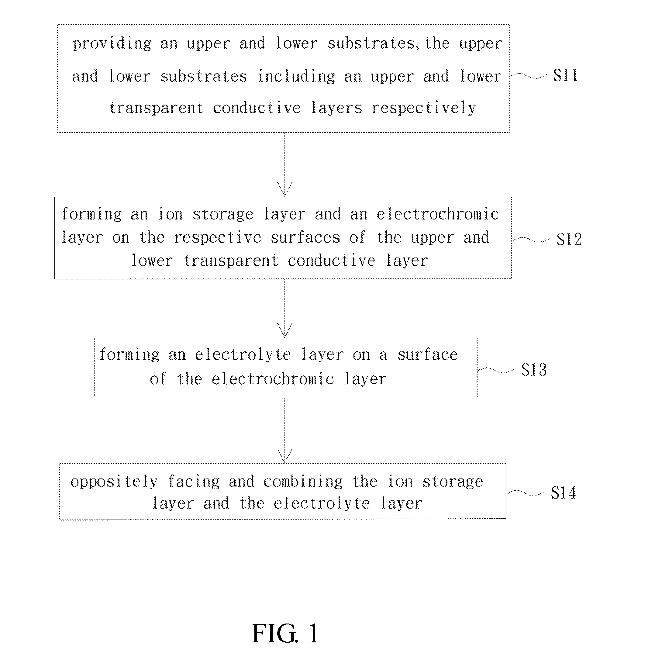
[0032]The advantages and features of the present invention will be fully understood by reference to the following two examples in conjunction with the accompanying drawings.

[0033]FIG. 1 is a flow chart of a fabrication method of an electrochromic element according to a preferred embodiment of the present invention; and

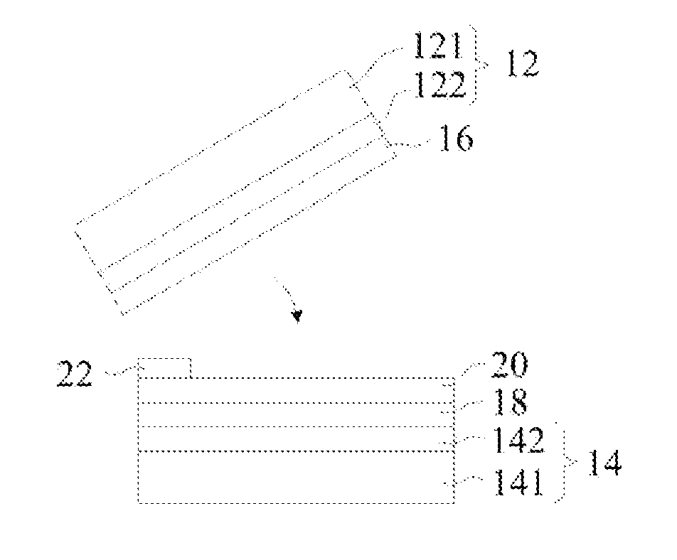
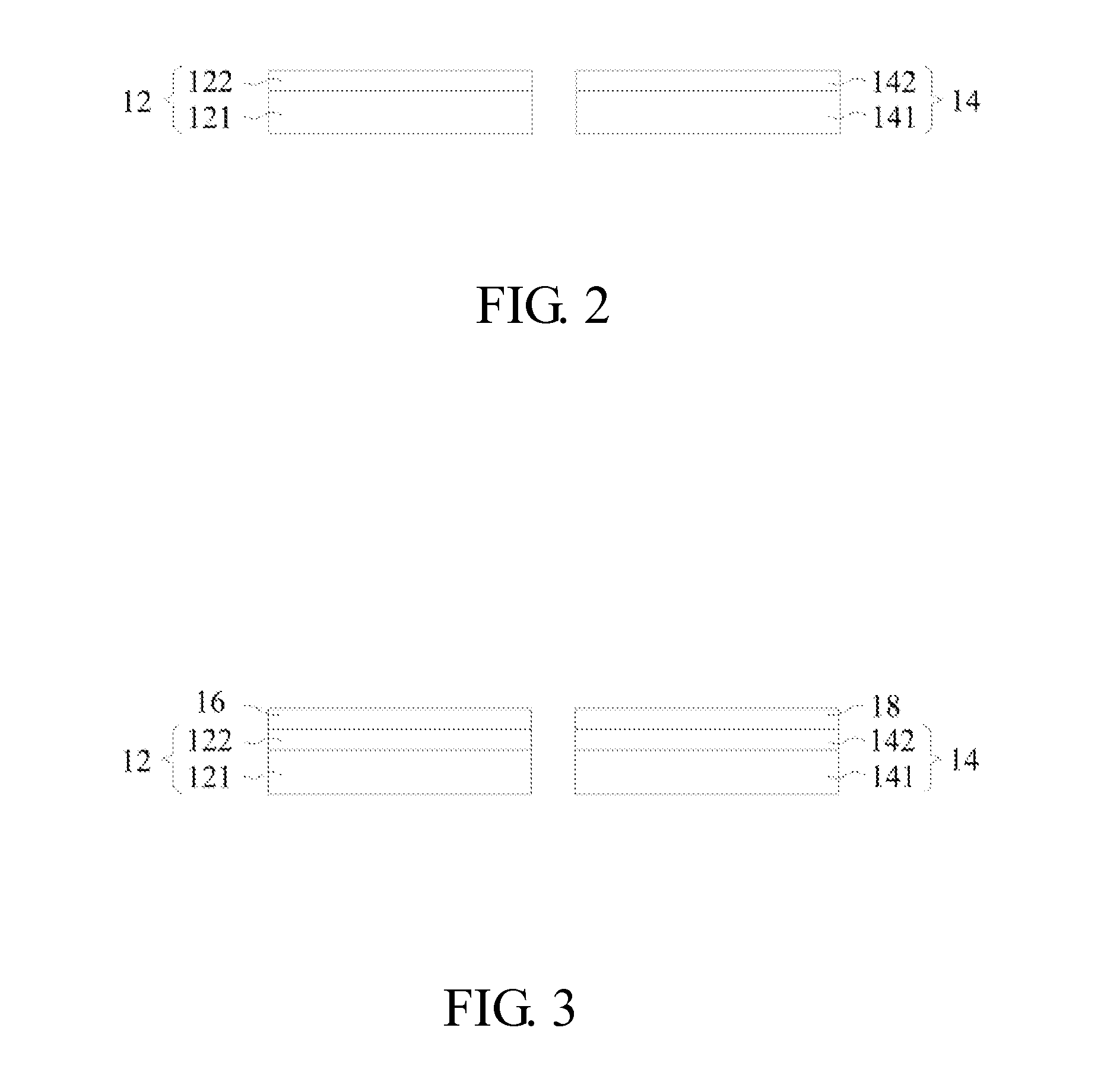
[0034]FIGS. 2-6 are views showing a process of fabricating an electrochromic element according to a preferred embodiment of the present invention.

[0035]As shown in FIGS. 1 and 2, in step S11, a first substrate 12 and a second substrate 14 are provided, wherein the first substrate 12 includes a first base layer 121 and a first transparent conductive layer 122, and the second substrate 14 includes a second base layer 141 and a second transparent conductive layer 142. The first base layer 121 and the second base layer 141 may be made of glass, plastics or metal. The metal may be aluminum, chromium, silver or nickel, and has a thickness of 1 um-100 um. The first transparen...


PUM

PropertyMeasurementUnit
transmittanceaaaaaaaaaa
angleaaaaaaaaaa

Abstract

A fabrication method of an electrochromic element includes the steps of: providing a first substrate and a second substrate, the first substrate including a first base layer and a first transparent conductive layer, the second substrate including a second base layer and a lower second transparent conductive layer; forming an ion storage layer on a surface of the upper first transparent conductive layer, and forming an electrochromic layer on a surface of the lower second transparent conductive layer; forming an electrolyte layer on a surface of the electrochromic layer; oppositely facing and combining the ion storage layer and the electrolyte layer in a gradually slantly manner by use of an assistant material disposed on corresponding peripheries of the electrolyte layer and the ion storage layer; and drying the combined electrolyte layer and the ion storage layer for complete manufacture of the electrochromic element as a finished product.

Description

BACKGROUND OF THE INVENTION[0001]1. Field of the Invention[0002]The present invention relates to a fabrication method of a color-changeable element, particularly to a fabrication method of an electrochromic element.[0003]2. Description of the Related Art[0004]Generally, a conventional electrochromic unit has a laminated structure, and at least one transparent electrode layer is layered on a side surface of the laminated structure. The conventional electrochromic unit generally further includes a couple of glass substrates. If the electrochromic unit is applied to a car-used rearview mirror, one of the glass substrates is able to reflex light. A transparent conductive layer is layered on one side surface of the glass substrates. For example, indium tin oxide (ITO) layer is coating on the side surface. The glass substrates oppositely face to each other and the electrochromic layer is attached therebetween, to form an electrochromic unit. The electrochromic unit is electrically connect...

Claims


Application Information

Patent Timeline
Patent Type & Authority Patents(United States)
IPC IPC(8): G02F1/15B32B33/00B32B38/00
CPCB32B38/00B32B33/00B32B2307/40G02F1/15
Inventor SHANG, YU CHUN
Owner IND TECH RES INST
Why Eureka
Try Eureka