Resonant pressure sensor and method of manufacturing the same

a technology of resonant pressure sensor and manufacturing method, which is applied in the direction of fluid pressure measurement, fluid pressure measurement by electric/magnetic elements, instruments, etc., can solve the problems of difficult control of thickness of several m to several tens of m, poor sensitivity, and degraded device characteristics of sensors, etc., to achieve excellent characteristics and degrade the effect of device characteristics

Active Publication Date: 2015-04-14
YOKOGAWA ELECTRIC CORP
View PDF24 Cites 1 Cited by
  • Summary
  • Abstract
  • Description
  • Claims
  • Application Information

AI Technical Summary

Benefits of technology

[0044]1) A structure in which a variation in sensitivity can be suppressed and controllability of a thickness of a diaphragm is excellent.
[0081]Generally, when the high-temperature process of 800° C. or more is executed after the resonant-type strain gauge, redistribution of impurity elements, rearrangement of atoms, or re-crystallization may occur, and thus device characteristics of a sensor may be degraded. The process of fabricating a diaphragm such that the room-temperature direct bonding process or the metal diffusion bonding process can be performed at a temperature of, for example, about 400° C. or less, and thus a creep of silicon or thermal distortion that adversely affects characteristics of a pressure sensor does not remain. Thus, it is possible to implement the fabricating method of the resonant pressure sensor having excellent characteristics.

Problems solved by technology

As a result, since the Q value of the resonant-type strain gauge element is lowered, characteristics such as input / output characteristics worsen.
However, the above-mentioned methods have the following problems.
H01-171337, since a diaphragm is formed using deep alkaline etching, it is difficult to control the thickness of several μm to several tens of μm in units of μm, and thus it is difficult to suppress a variation in sensitivity.
Further, since a gap is formed using a machined part, it is difficult to form a small gap of several tens of μm or less with a high degree of accuracy, and there is a limitation to suppressing resonance of a diaphragm.
Further, since a machined part is used, a foreign substance may be mixed in when a gap is formed.
In this case, a movable range of a diaphragm is limited, and thus characteristics such as input / output characteristics may be affected.
In addition, it is difficult to freely select the shape of a diaphragm due to influence of crystal surface orientation by alkaline etching when a diaphragm is formed.
For this reason, there is a design restriction to the shape of a diaphragm, and it is difficult to design the shape of a diaphragm with flexibility.
H02-032224, since a diaphragm is formed using deep alkaline etching, it is difficult to control the thickness of several μm to several tens of μm in unit of μm.
Further, when a gap is formed, it is difficult to process a concave portion by alkaline etching with a high degree of accuracy, and a processing error of a facing convex part lowers the accuracy.
Thus, it is difficult to form a gap of several μm with a high degree of accuracy, and there is a limitation to suppressing resonance of a diaphragm.
Further, it is difficult to freely select the shape of a diaphragm due to influence of crystal surface orientation by alkaline etching when a diaphragm is formed.
Thus, when a diaphragm is designed, there is a restriction to the shape of a diaphragm, and it is difficult to design a diaphragm with a flexible shape.
For this reason, it is difficult to design a diaphragm with a flexible shape which is not restricted by crystal orientation.
First, the deep alkaline etching is easily affected by the temperature of a chemical, and thus it is difficult to control the thickness.
Further, even though an etching amount is large, the accuracy required for a film thickness of a diaphragm is high, and thus it is difficult to control.
In other words, there is large restriction on the design of a sensor with a pressure range in which displacement of 4 μm or more is necessary.
Thus, in order to migrate from trail production to commercialization, an extraordinary amount of time is inevitably expended.
H06-244438 is affected by the plane orientation, and thus it is difficult to design the flexible shape which is not restricted by crystal orientation.

Method used


Image

  • Resonant pressure sensor and method of manufacturing the same
  • Resonant pressure sensor and method of manufacturing the same
  • Resonant pressure sensor and method of manufacturing the same

Examples


first preferred embodiment

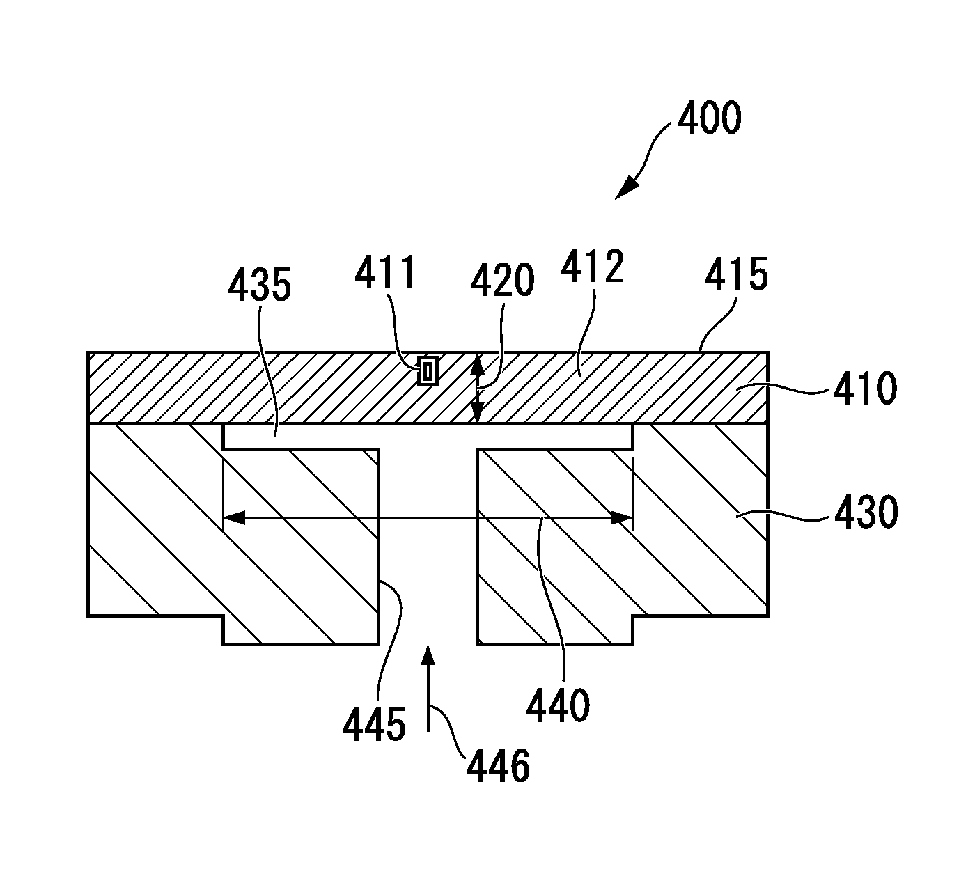
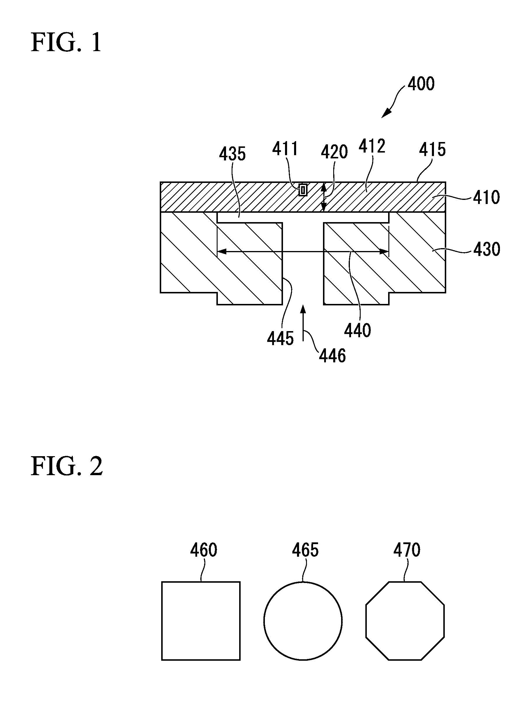
[0102]FIG. 1 is an explanatory diagram illustrating a configuration of a resonant pressure sensor in accordance with a first preferred embodiment of the present invention. FIG. 2 is an explanatory diagram illustrating shapes of the diaphragm illustrated in FIG. 1.

[0103]The resonant pressure sensor includes a sensor substrate 410 and a base substrate 430. The sensor substrate 410 and the base substrate 430 are made of silicon. Resonant-type strain gauge elements 411 are disposed on one surface of the sensor substrate 410, and the other surface of the sensor substrate 410 remains polished at the thickness corresponding to a diaphragm 412. The other surface of the sensor substrate 410 bonds directly with one surface of the base substrate 430.

[0104]A concave portion 435 is formed in a portion of the base substrate 430 that bonds with the sensor substrate 410. The concave portion 435 substantially forms the diaphragm 412 in the sensor substrate 410. The concave portion 435 has a predeter...

second preferred embodiment

[0132]FIG. 5 is an explanatory diagram illustrating a configuration of a resonant pressure sensor in accordance with a second preferred embodiment of the present invention. FIG. 6 is an explanatory diagram illustrating shapes of the diaphragm illustrated in FIG. 5.

[0133]The resonant pressure sensor includes a sensor substrate 610 and a base substrate 630. The sensor substrate 610 and the base substrate 630 are made of silicon. Resonant-type strain gauge elements 611 are disposed on one surface of the sensor substrate 610, and the other surface of the sensor substrate 610 is polished at the thickness corresponding to a diaphragm 612 to form a concave portion 635. The other surface of the sensor substrate 610 bonds directly with one surface of the base substrate 630.

[0134]The concave portion 635 is formed in a portion of the sensor substrate 610 that bonds with the base substrate 630. The concave portion 635 substantially forms the diaphragm 612 in the sensor substrate 610. The concav...

third preferred embodiment

[0170]FIG. 9 is an explanatory diagram illustrating a configuration of a resonant pressure sensor in accordance with a third preferred embodiment of the present invention. FIG. 10 is an explanatory diagram illustrating a shapes of the diaphragm illustrated in FIG. 9.

[0171]The resonant pressure sensor 800 includes a sensor substrate 810 and a base substrate 830. A conducting hole 845 is formed in the base substrate 830 by plasma etching, alkaline etching, or the like. The conducting hole 845 can have any shape appropriate for a conducting hole. A resonant-type strain gauge element 811 is fabricated on an upper surface 815 of the diaphragm.

[0172]The thickness of the diaphragm is decided depending on the thickness of the sensor substrate 810. For this reason, the thickness 820 of the diaphragm is adjusted such that grinding / polishing is performed up to a desired thickness. Since the grinding / polishing amount can be finely adjusted for each wafer, the thickness of each wafer can be cont...


PUM

PropertyMeasurementUnit
thicknessaaaaaaaaaa
displacementaaaaaaaaaa
sizeaaaaaaaaaa

Abstract

A resonant pressure sensor including one or more resonant-type strain gauges arranged on a diaphragm may include a sensor substrate made of silicon and including one surface on which one or more resonant-type strain gauge elements are arranged and the other surface which is polished to have a thickness corresponding to the diaphragm, a base substrate made of silicon and including one surface directly bonded with the other surface of the sensor substrate, a concave portion formed in a portion of the base substrate bonding with the sensor substrate, substantially forming the diaphragm in the sensor substrate, and including a predetermined gap that does not restrict a movable range of the diaphragm due to foreign substances and suppresses vibration of the diaphragm excited by vibration of the resonant-type strain gauge elements, one or more conducting holes, and a fluid.

Description

BACKGROUND OF THE INVENTION[0001]1. Field of the Invention[0002]The present invention relates to a resonant pressure sensor. More specifically, the present invention relates to a resonant pressure sensor which is high in measurement accuracy, simple to fabricate, and low in cost.[0003]Priority is claimed on Japanese Patent Application No. 2011-183857, filed Aug. 25, 2011, the content of which is incorporated herein by reference.[0004]2. Description of the Related Art[0005]All patents, patent applications, patent publications, scientific articles, and the like, which will hereinafter be cited or identified in the present application, will hereby be incorporated by reference in their entirety in order to describe more fully the state of the art to which the present invention pertains.[0006]FIG. 13 is an explanatory diagram illustrating a main part of a resonant pressure sensor in accordance with the related art, which is disclosed, for example, in Japanese Unexamined Utility Model App...

Claims


Application Information

Patent Timeline
Patent Type & Authority Patents(United States)
IPC IPC(8): G01L11/00G01L9/00
CPCG01L9/0016G01L9/0045
Inventor YOSHIDA, YUUSAKUYOSHIDA, TAKASHISUZUKI, HIROSHIYOSHITA, SHUHEITERASHITA, HISASHI
Owner YOKOGAWA ELECTRIC CORP
Why Eureka
Try Eureka