Infrared detection of defects in wind turbine blades

a technology of infrared detection and wind turbine blades, which is applied in the direction of mechanical roughness/irregularity measurement, optical radiation measurement, instruments, etc., can solve the problems of difficulty in detecting the presence of defects, the time required to complete a measurement is too long to be operationally attractive, and the method is generally limited, so as to reduce the temperature inside the blade. , the effect of reliably and quickly detecting defects

Inactive Publication Date: 2015-04-14
KURION INC
View PDF12 Cites 26 Cited by
  • Summary
  • Abstract
  • Description
  • Claims
  • Application Information

AI Technical Summary

Benefits of technology

[0014]The invention described in FIG. 4 provides a method and an apparatus for reliably and quickly detecting defects throughout the entire thickness of the composite materials comprising a wind turbine blade or similar type of structure using an IR camera. The preferred embodiment of the present invention requires a means of cooling air 86 and blowing this cooled air 84 through the inside region of the blade to lower the temperature inside the blade below the temperature of the composite material and the outside ambient temperature. This produces identifiable temperature changes on the surface of the composite structure that can be detected with an uncooled IR camera 80. The IR intensity changes associated with the defects can be identified by visual inspection of an IR image or by computer 82 using a noise cancelled IR image. Once the IR detectable signals are produced due to the cooling method, a hand-held IR camera can be moved continuously and rapidly along the entire length of the blade to record IR images of the surface to be used in either the visual or automatic inspection process.

Problems solved by technology

While IR methods have been used to detect defects such as these in wind turbine blades, these methods have generally been limited to defects near the surface.
In addition, for some of the methods, the time required to complete a measurement has been too long to be operationally attractive.
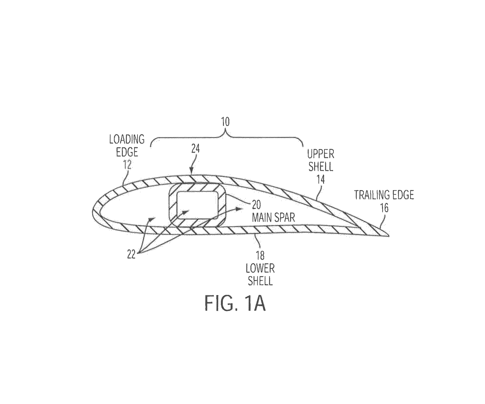
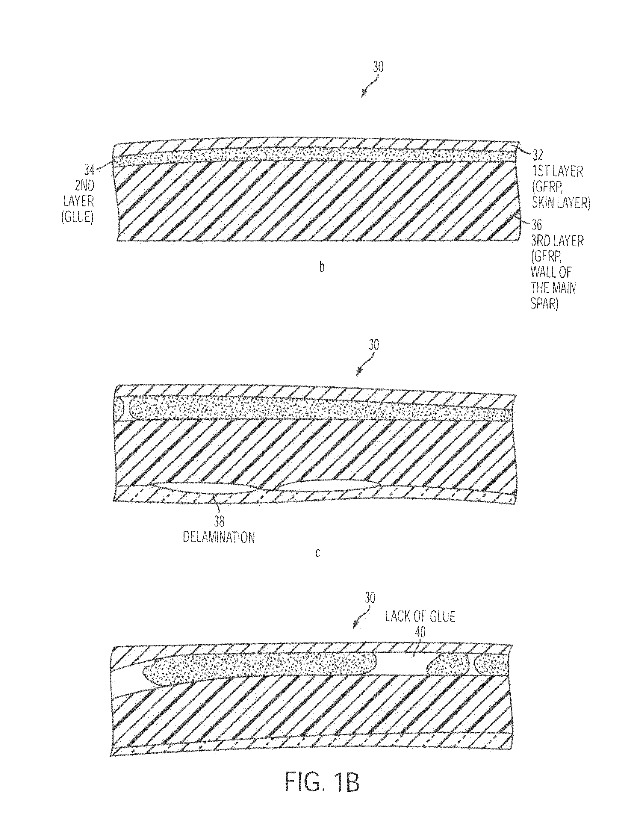
This method, however, will have difficulties in detecting the presence of defects 68 in the deepest portion of the composite structure, particularly in the deeper portions of the third layer 68.
The model results also suggest that the method will have problems detecting defects closer to the inside surface of the composite deep within the third layer of the composite.

Method used


Image

  • Infrared detection of defects in wind turbine blades
  • Infrared detection of defects in wind turbine blades
  • Infrared detection of defects in wind turbine blades

Examples


Embodiment Construction

[0031]The method and apparatus of the preferred embodiment of the present invention is illustrated in FIG. 4. Air cooler than the temperature of the composite and the ambient air temperature is blown through the inside region of the wind turbine blade using an air conditioning unit 86 and a blower 84. The difference in the temperature of the cooler air inside the blade and the temperature of the ambient air outside the blade is sufficient to produce a change in the surface temperature of the composite associated with a defect anywhere in the composite that is strong enough to be detected with an inexpensive, uncooled IR camera 80. A hand-held IR camera 80 can be moved continuously and rapidly along the entire length of the blade to record images of the surface. The defects can be identified by visual inspection or by computer 82 using a noise cancelled IR image.

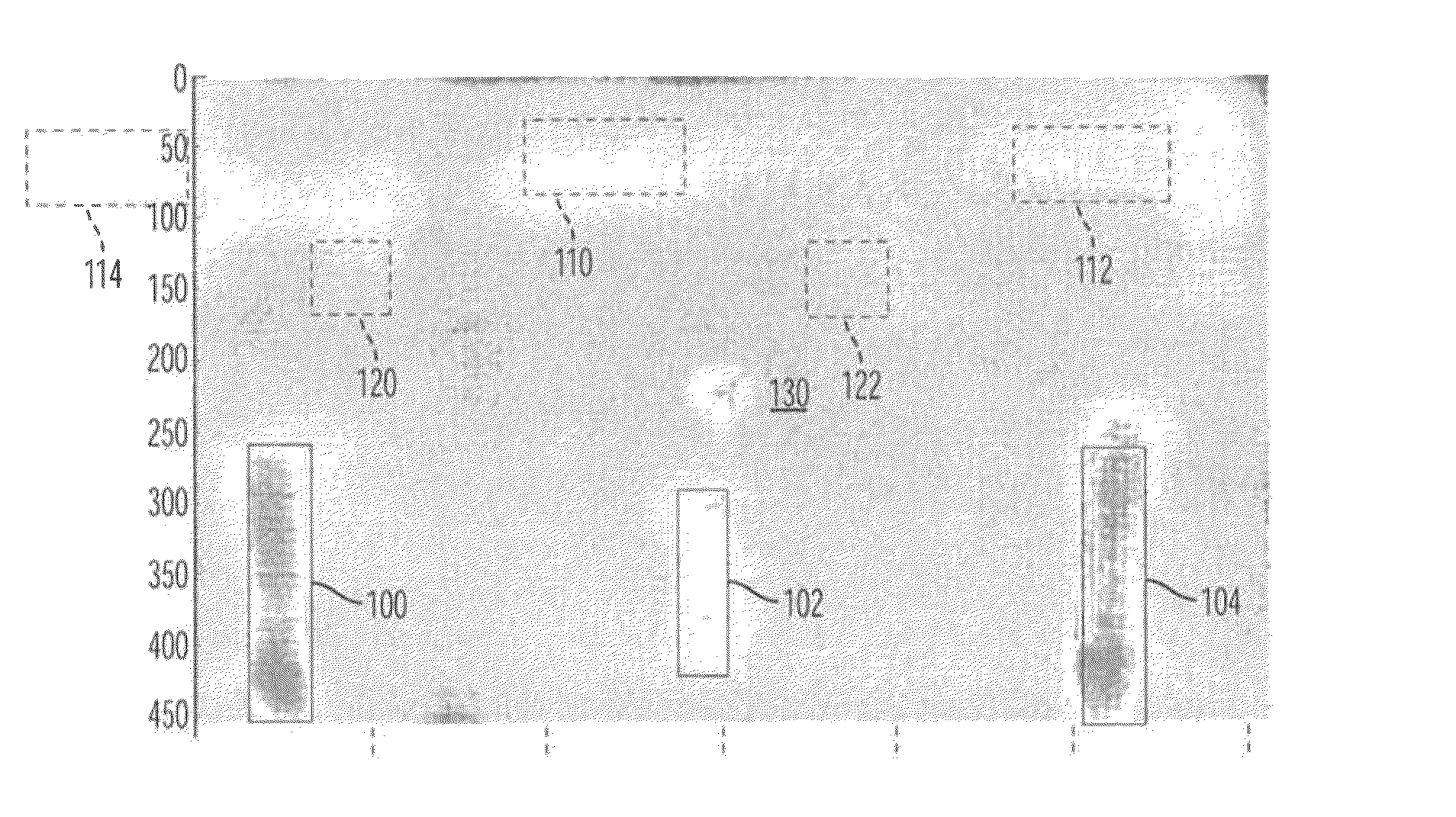
[0032]FIGS. 5 and 8 illustrate the temperature change on the surface of the composite shown in FIG. 2 for a 6° C. differenc...


PUM

PropertyMeasurementUnit
temperatureaaaaaaaaaa
thickaaaaaaaaaa

Abstract

A method and an apparatus for detecting defects in the composite materials of a wind turbine blade or similar type of structure using an infrared (IR) camera. The temperature of the wind turbine blade is changed in such a way as to produce IR intensity changes in the region of the defect that can be visually detected or detected using a computer and signal processing algorithms. The same approach will work on other composite structures such as those found on aircraft.

Description

RELATED APPLICATION[0001]This application claims the benefit of U.S. Provisional Patent Application Ser. No. 61 / 404,356 filed Oct. 1, 2010.BACKGROUND[0002]1. Field of the Invention[0003]A method and an apparatus for detecting defects in the composite materials of a wind turbine blade or similar type of structure using an infrared (IR) camera, where the defects may be separation of the layers between different composite materials, waves or wrinkles in the composite layers, separation of the layers within the composite material, layers in the composite where the resin did not fully wet the cloth layer, or liquid such as water that may have infiltrated such layer defects. The temperature of the wind turbine blade relative to the ambient temperature is changed in such a way as to produce IR intensity changes in the region of the defect that can be visually detected, or detected using a computer and a signal processing algorithm. The same approach will work on other composite structures ...

Claims


Application Information

Patent Timeline
Patent Type & Authority Patents(United States)
IPC IPC(8): G01N25/00G01B5/28G01J5/00
CPCG01J5/0088G01N25/72G01J2005/0077
Inventor MARESCA, JR., JOSEPH W.BRATTON, WESLEY L.LEUSCHEN, WILHELMINA C.ROHRIG, DAVID A.
Owner KURION INC
Why Eureka
Try Eureka