Non-radioactive ion source using high energy electrons

a high-energy electron and electron source technology, applied in the field of chemical analysis, can solve the problems of difficult to avoid contamination by explosive particles, low vapor pressure, instrument contamination and confusion, etc., and achieve the effects of high energy electrons, high energy, and high energy

Active Publication Date: 2015-04-14
LEIDOS SECURITY DETECTION & AUTOMATION INC
View PDF27 Cites 12 Cited by
  • Summary
  • Abstract
  • Description
  • Claims
  • Application Information

AI Technical Summary

Problems solved by technology

Such mixtures may cause instrument contamination and confusion due to the presence of molecular interferents producing signatures that are either identical to that of the chemical compounds of interest or unresolved by the analytical instrument due to its limited resolution.
An interferent can also manifest its presence by affecting the limit of detection of the compound of interest.
The assumption being that due to their high sticking coefficient it is difficult to avoid contamination by explosives particles during the process of handling a bomb.
The same high sticking coefficient results in extremely low vapor pressures and hence makes their detection difficult.
Since different molecules may have similar drift times, IMS inherently has limited chemical specificity and therefore is vulnerable to interfering molecules.

Method used


Image

  • Non-radioactive ion source using high energy electrons
  • Non-radioactive ion source using high energy electrons
  • Non-radioactive ion source using high energy electrons

Examples


Embodiment Construction

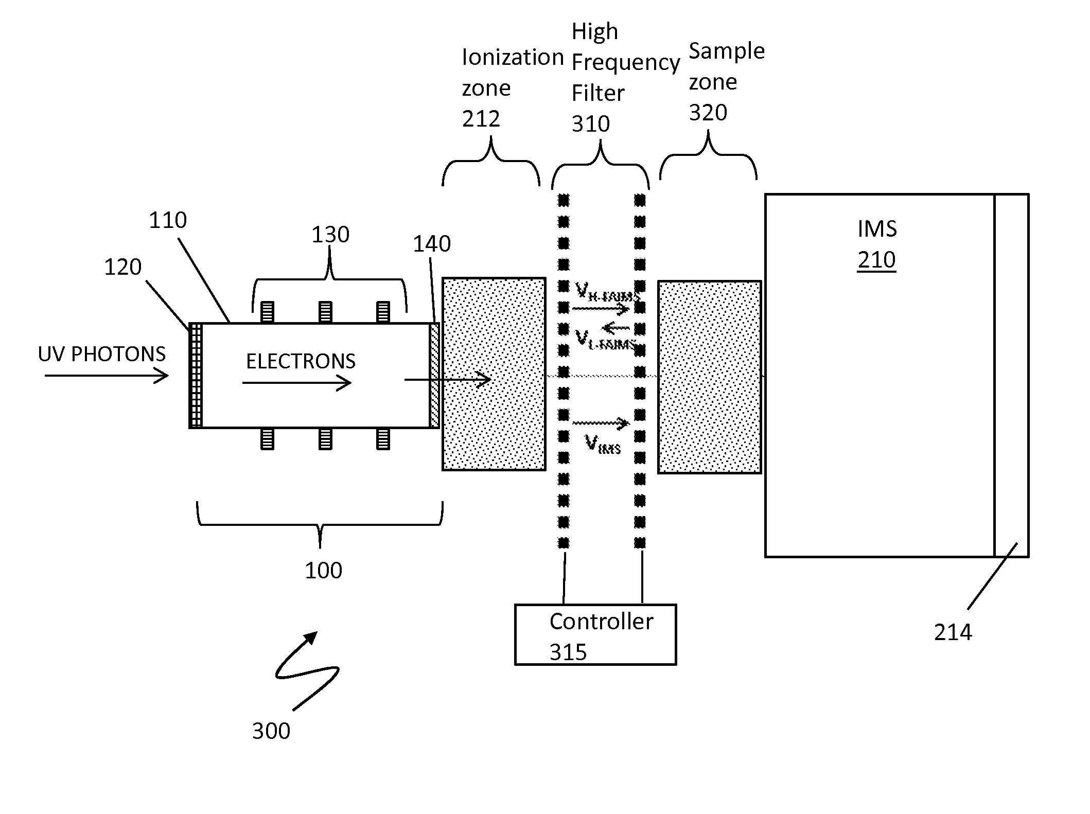
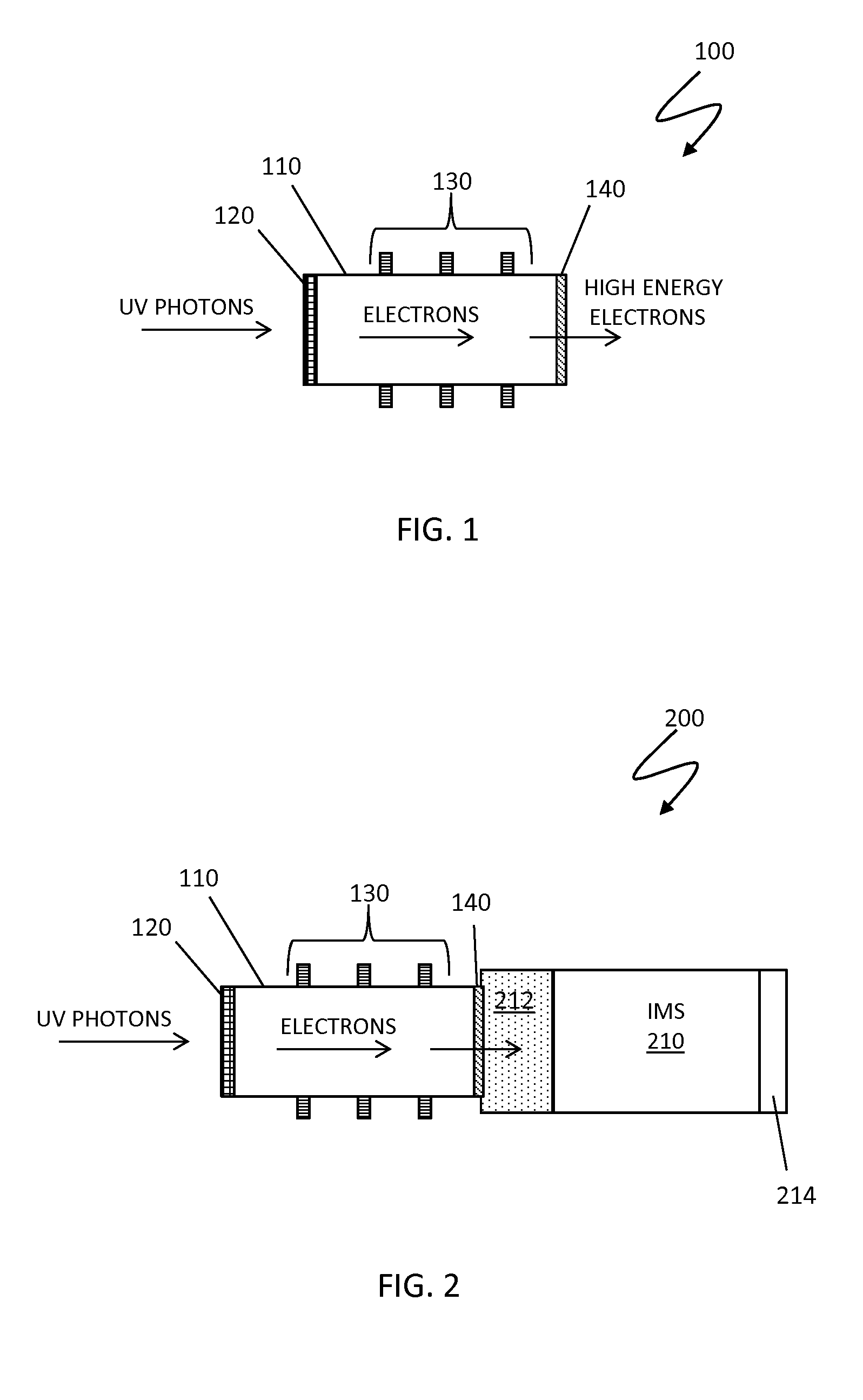
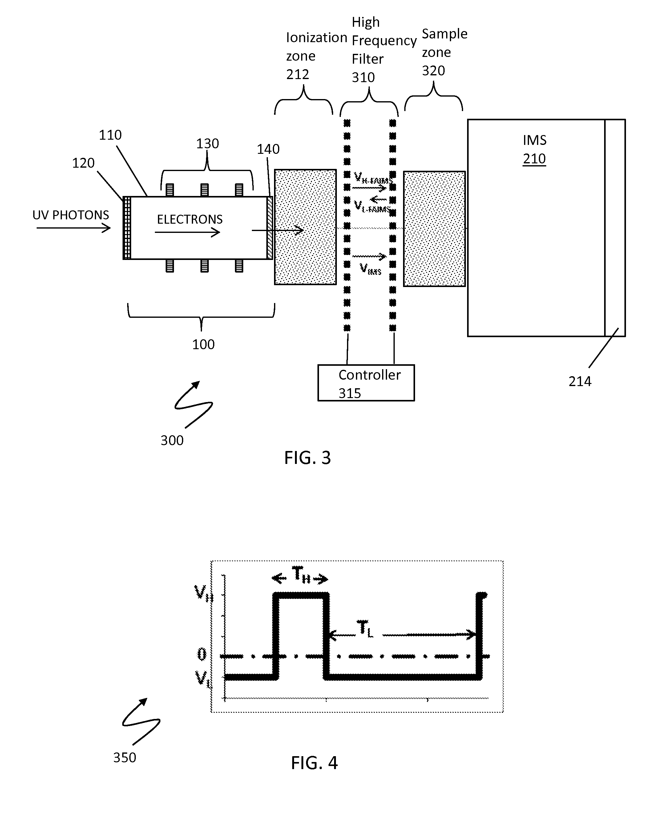
[0019]FIG. 1 is a schematic illustration showing a high energy electron source device 100 for producing continuous or pulsed source of high energy electrons at atmospheric or near atmospheric pressure according to an embodiment of the system described herein. According to the system described herein, high energy electrons may be used to efficiently ionize analyte molecules in ambient air through collisions with reactant ions. Compared to conventional radioactive emitters such a non-radioactive high energy ion source eliminates the health hazards, travel and legal restrictions as well as site specific exclusions. Furthermore, an ability to generate packets of electrons may eliminate the need for gates when such a device is in connection with an ion source for pulsed analytical stages, such as used in ion mobility spectrometers (IMS). According to an embodiment, the device 100 may include an electron emitter 120, high energy electron optics 130, and a thin membrane 140 disposed on an ...


PUM

PropertyMeasurementUnit
electric fieldaaaaaaaaaa
thicknessaaaaaaaaaa
transparentaaaaaaaaaa

Abstract

A system and method for producing a continuous or pulsed source of high energy electrons at or near atmospheric pressure is disclosed. High energy electrons are used to ionize analyte molecules in ambient air through collisions with reactant ions. The device includes an electron emitter, electron optics, and a thin membrane in an evacuated tube. The electron emitter may include a photocathode surface mounted on an optically transparent window and an external source of UV photons. The transparent window may include a UV transparent window mounted on an evacuated tube and / or the evacuated tube may be a transparent tube on which a photocathode surface film is deposited. The electron optics may include successive electrodes biased at increasing voltages. The membrane may include a material transparent or semi-transparent to energetic electrons. Upon impacting the membrane, continuous or pulsed electron packets are partially transmitted through to a high pressure ionization region.

Description

RELATED APPLICATIONS[0001]This application claims priority to U.S. Provisional App. No. 61 / 679,976, filed Aug. 6, 2012, entitled “High Energy Electron Source,” which is incorporated herein by reference.TECHNICAL FIELD[0002]This application is related to the field of chemical analysis and, in particular, ion mobility spectrometry.BACKGROUND OF THE INVENTION[0003]In field applications, chemical analysis instruments may be confronted with various complex mixtures regardless of indoor or outdoor environments. Such mixtures may cause instrument contamination and confusion due to the presence of molecular interferents producing signatures that are either identical to that of the chemical compounds of interest or unresolved by the analytical instrument due to its limited resolution. An interferent can also manifest its presence by affecting the limit of detection of the compound of interest. A multi-stage analysis approach may therefore be used to reduce the chemical noise and produce enou...

Claims


Application Information

Patent Timeline
Patent Type & Authority Patents(United States)
IPC IPC(8): H01J27/00G01N27/62H01J3/02H01J27/20H01J29/04H01J31/04H01J33/02
CPCH01J31/04H01J29/04H01J27/205H01J3/021H01J33/02G01N27/624G01N27/64
Inventor IVASHIN, DMITRIY V.BOUMSELLEK, SAID
Owner LEIDOS SECURITY DETECTION & AUTOMATION INC
Why Eureka
Try Eureka