Device for self-aligning and affixing of a microchannel plate in a micro-system and method the same

a micro-system and micro-channel plate technology, applied in the field of micro-electromechanical systems, can solve the problems of inability to produce all the components of a micro mass spectrometer, general restrictions on the mounting device and the fixture in the microoptical, and irreversible connection, and achieve the effect of high aspect ratio

Inactive Publication Date: 2015-04-14
BAYER AG +1
View PDF12 Cites 0 Cited by
  • Summary
  • Abstract
  • Description
  • Claims
  • Application Information

AI Technical Summary

Benefits of technology

[0035]Metallic structures with a high aspect ratio can be realized by electrolytic growth in thick photoresists (>100 μm) with comparable accuracy (UV LIGA). Using thin-film technologies such as high-vacuum evaporation and cathode sputtering, PVD processes or chemical vapor deposition (CVD processes) preferably in plasma in combination with photolithography and etching techniques, it is possible to integrate on these substrates functional layers such as metallizations, hydrophobic or hydrophilic surfaces and functional elements such as valve seals and membranes, heating elements, temperature, pressure and flow sensors in a fully process-compatible technology. By using carbon nanotubes that preferably undergo self-assembly in defined regions in deposition or patterning processes, but also silicon needles or metal cluster structures, it is possible to integrate functions based on these nanostructures into microsystems.

Problems solved by technology

It has not been possible hitherto to produce all the components of a micro mass spectrometer monolithically in one workpiece.
Mounting devices and fixtures in microoptical are generally restricted to mechanical structures that predominantly serve for the precise positioning of the components.
What is disadvantageous is, inter alia, that the component is irreversibly connected to a substrate; it is not possible to exchange the component.
EP1345843B1 describes a device for securing totally released microcomponents, which, however, does not enable a component to be mounted in a self-aligning fashion.

Method used


Image

  • Device for self-aligning and affixing of a microchannel plate in a micro-system and method the same
  • Device for self-aligning and affixing of a microchannel plate in a micro-system and method the same
  • Device for self-aligning and affixing of a microchannel plate in a micro-system and method the same

Examples


Embodiment Construction

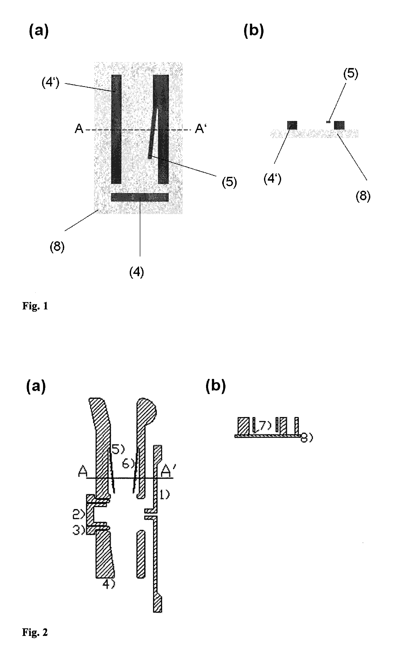
[0058]FIG. 1 shows a schematic illustration of a simple embodiment of the fixture according to the invention (a) in plan view, (b) in cross section through the connecting line through the points A and A′ in FIG. 1(a).

[0059]The embodiment shown has two stops (4, 4′) and a spring structure (5), which are applied on a non-conductive substrate (8), an excerpt from which is shown here. A component can be introduced from above in FIG. 1(a) into the region between the stop (4′) and the spring structure (5). The component is pressed against the stop (4′) in the course of being pushed in by the spring structure and its position in this dimension is defined. The component is pushed into the fixture until it extends against the stop (4). Said stop (4) limits the displacement in a further dimension. The component is prevented from slipping out by the spring force of the spring structure (5). The component can, however, be removed in a reversible manner.

[0060]FIG. 2 schematically shows a preferr...


PUM

PropertyMeasurementUnit
diameteraaaaaaaaaa
diameteraaaaaaaaaa
electrical conductivityaaaaaaaaaa

Abstract

A device and/or method mount and affix a microchannel plate in a micro system. The device and/or method has at least one conductive spring structure, formed to accept a microchannel plate, for aligning, fixing and making electrical contact with the microchannel plate. The device and/or method also has at least one stop against which the microchannel plate is pushed or pressed when affixed by at least one conductive spring structure, wherein the at least one conductive spring structure and the at least one stop are being applied on a non-conductive substrate.

Description

[0001]This is an application filed under 35 USC §371 of PCT / EP2009 / 001088, claiming priority to DE 10 2008 011 972.5 filed on Feb. 29, 2008.BACKGROUND OF THE INVENTION[0002](1) Field of the Invention[0003]The present invention is concerned generally with the field of microelectromechanical system (MEMS). The present invention relates to a fixture for use in microsystems, in particular for the self-aligning mounting and fixture of microchannel plates, and to a device at least comprising a fixture according to the invention and a microchannel plate.[0004](2) Description of Related Art[0005]Microsystems engineering combines methods from microelectronics, micromechanics, microfluidics and microoptics, but also developments in informatics, biotechnology and nanotechnology, by combining developments and structures from these fields to form new systems. The dimensions of the function-determining structures lie in the micrometers range, which can be used as delimitation with respect to nano...

Claims


Application Information

Patent Timeline
Patent Type & Authority Patents(United States)
IPC IPC(8): H05K1/11H05K1/14B81C3/00H01J43/24H01J49/00
CPCB81C3/008H01J43/246H01J49/0018B81C2203/051H01L2924/0002H01L2924/00
Inventor HAUSCHILD, JAN-PETERWAPELHORST, ERICMULLER, JORG
Owner BAYER AG
Why Eureka
Try Eureka