Method and apparatus for fabricating large scale integrated airfoils

a technology of airfoil and airframe, which is applied in the field of large-scale integrated airfoil fabrication methods and equipment, can solve the problems of increased part count, high labor cost of fastener drilling and assembly, and use of fasteners, and achieves the effects of reducing or eliminating fasteners, low cost, and minimal tooling

Active Publication Date: 2015-04-28
THE BOEING CO
View PDF10 Cites 7 Cited by
  • Summary
  • Abstract
  • Description
  • Claims
  • Application Information

AI Technical Summary

Benefits of technology

[0008]The disclosed embodiments provide a method and apparatus for fabricating large scale integrated composite structures such as airfoils which employ co-bonding of components in order to reduce or eliminate fasteners and achieve a desired dimensional stability with relatively minimal, light weight tooling. In one embodiment, airfoil boxes are fabricated using pre-cured skins and spar webs that are assembled with uncured spar chords using relatively simple and inexpensive tooling. The pre-cured skins and spars are combined with simple internal tooling in an integrated manner that allows them to function as the final bond tool themselves. Final curing may require autoclave forces to be applied only to the area of the spar cords chords, and the need for the entire assembly to react these large autoclave forces is reduced or eliminated. In some applications, depending on the material systems being used, final curing may be carried out at or near atmospheric pressure in an oven. The final cure tooling requires no OML (outer mold line) definition or extensive support of large structures. During autoclave curing, the uncured spar chords are free to move in response to autoclave pressure which causes the uncured spar chords to adapt and mold themselves to the IML (inner mold line) of the skin, thereby providing good fit-up between the spars and the skin. The use of pre-cured skins and spar webs, along with integrated tooling and special bagging techniques, simplify large scale final cure processing, while greatly reducing the amount of vacuum bagging and associated complex tools. Also, the integrated tooling allows handling and indexing of thin parts such as the spar chords with reduced risk of damage, and provides continuous support of large loose, uncured details (e.g. spar chords) with minimal need for auxiliary equipment. The disclosed method and apparatus allow NDI of composite components before final bonding operations and may significantly reduce the need for rework.
[0009]Another advantage of the disclosed embodiments lies in the fact that pre-cured skins and spars can be net trimmed prior to final bonding operations. Left hand and right hand large scale integrated structures can be built on the same final bond fixture. Vacuum bagging is simplified and may carried out using reusable bagging concepts. Final cure cycles may be significantly reduced compared to large typical CFPR (carbon fiber reinforced plastic) integrated structures because of the weight reduction of final bond tooling.

Problems solved by technology

The use of fasteners has a number of disadvantages, including but not limited to increased part count, higher labor costs for fastener drilling and assembly, added weight to the structure and the susceptibility of fasteners to lighting strikes.
Some of the disadvantages of mechanical assembly using fasteners may be overcome by integrating composite components to reduce part count, however large scale integration of composite structures may present several challenges.
For example, although large scale integration may reduce the number of parts, some parts may require special storage, handling and tracking prior to a final bonding operation.
Also, the tooling required for large scale integration may be relatively complicated, heavy and costly.
For example, it may be difficult to achieve the desired dimensional control of large scale integrated structures without the use of complicated and expensive matched die tooling.
Additionally, final bond tooling may require additional heavy and expensive reinforcement structures in order to withstand the forces imposed by autoclave processing.
Large scale integrated structures may require a correspondingly large area of vacuum bagging, which may be labor intensive to install and may present the opportunity for bag leaks that may be difficult to detect and repair prior to curing.
Still another challenge presented by large scale integration involves the fact that certain NDI (non-destructive inspection) operations may be carried out only after final cure.
NDI performed after the final cure step may not allow early detection of parts requiring rework, and may result in expensive repairs or scrapping of a relatively large part or assembly due to a nonconformity in a relatively small portion.

Method used


Image

  • Method and apparatus for fabricating large scale integrated airfoils
  • Method and apparatus for fabricating large scale integrated airfoils
  • Method and apparatus for fabricating large scale integrated airfoils

Examples


Embodiment Construction

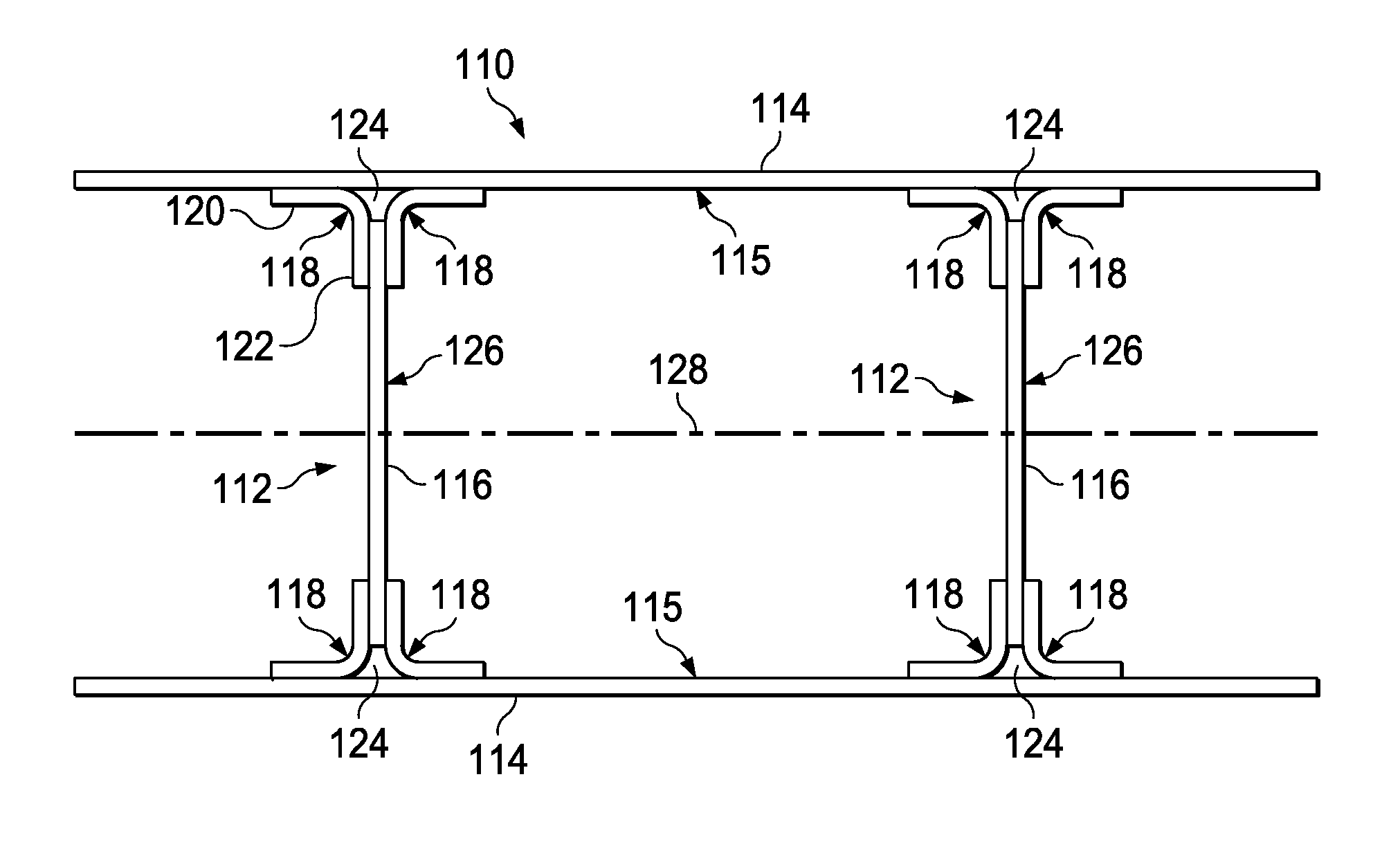
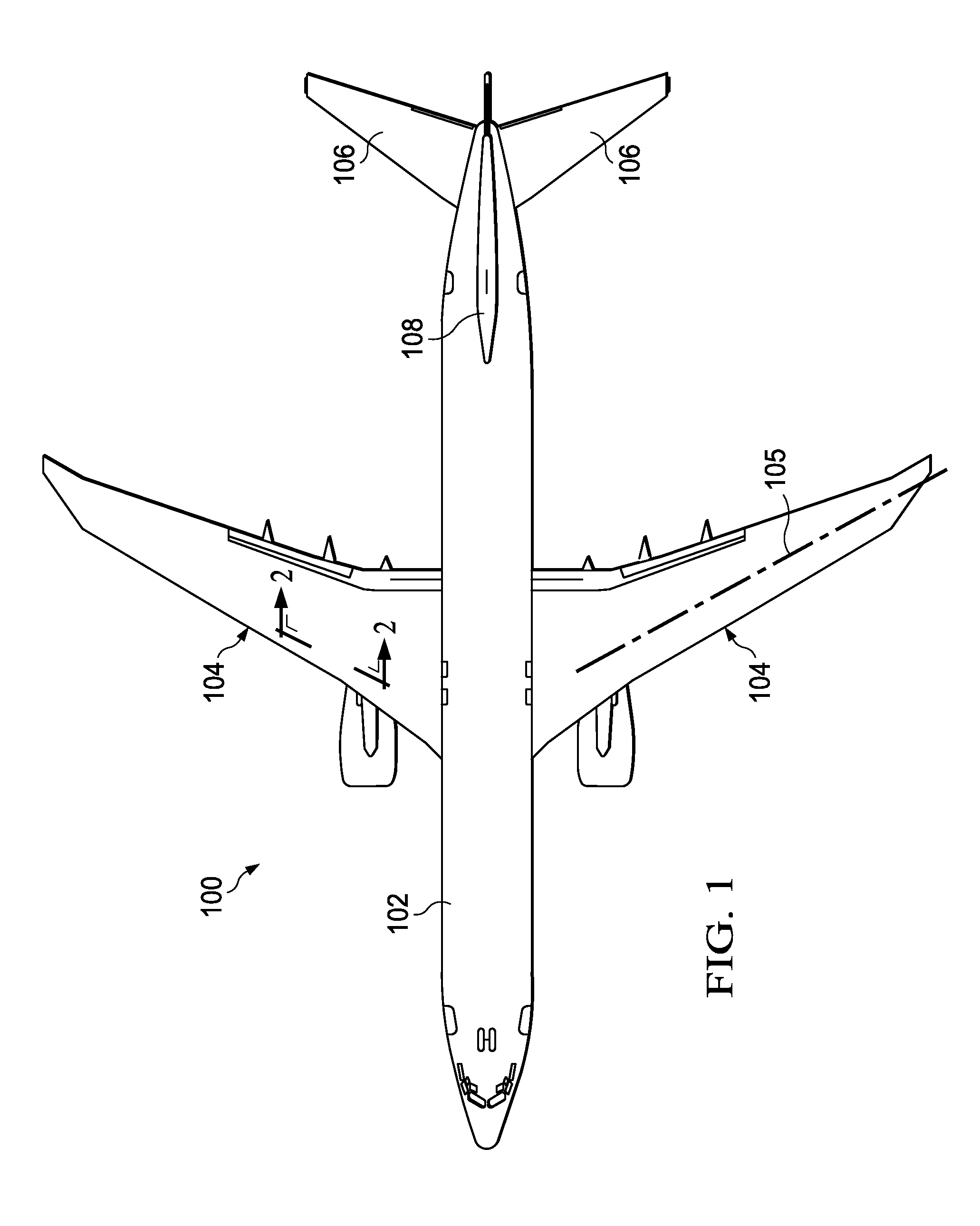
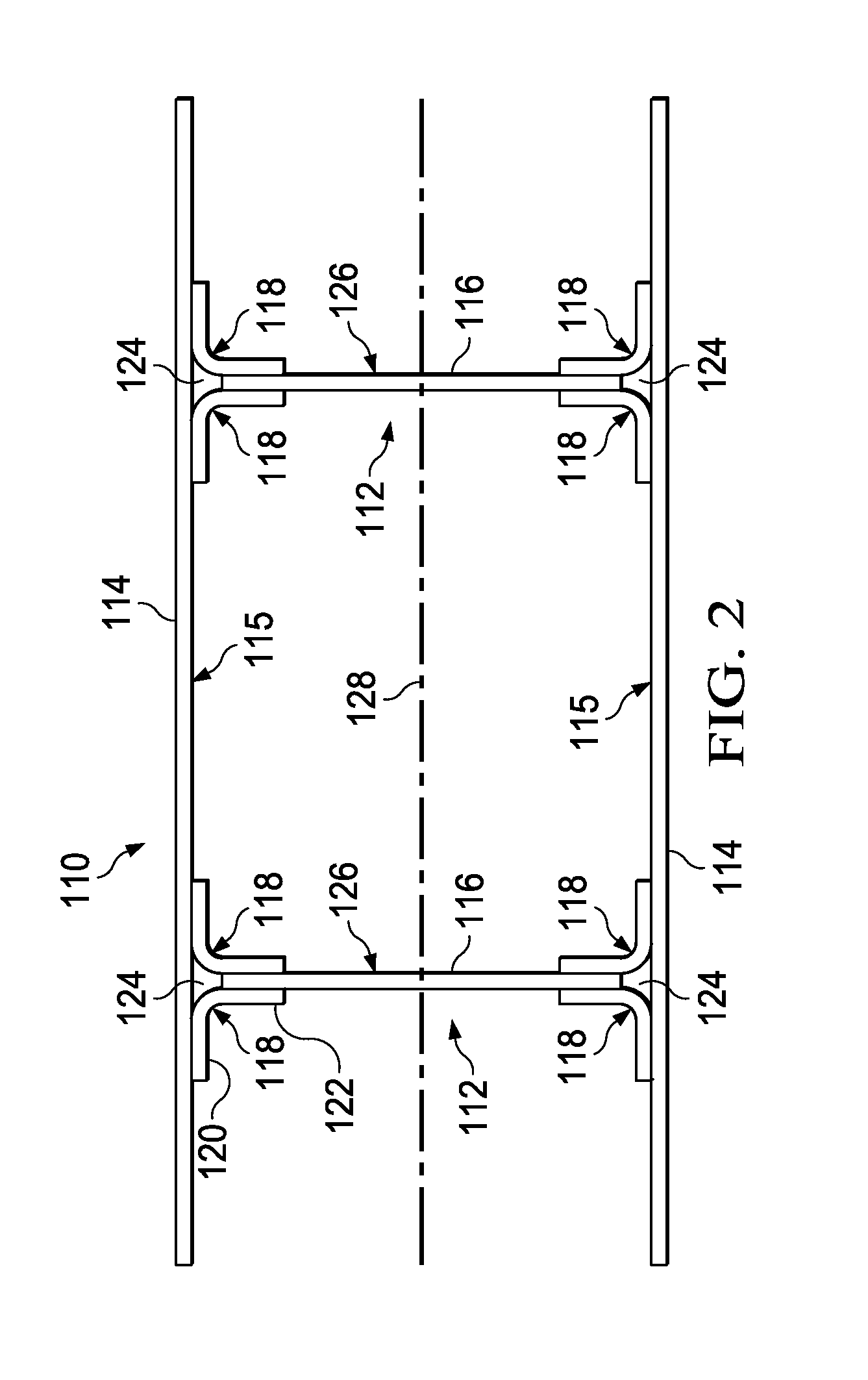
[0061]Referring first to FIG. 1, an aircraft 100 includes a fuselage 102 having one or more airfoils, which in the illustrated example comprise wings 104, horizontal stabilizers 106 and vertical stabilizer 108. FIG. 2 illustrates a typical airfoil box 110 which may form a portion of, for example and without limitation, each of the wings 104 of the aircraft 100 shown in FIG. 1. The airfoil box 110 extends in the span-wise direction 105 shown in FIG. 1 (into the paper in FIG. 2) of a wing 104, and broadly includes one or more spars 112 sandwiched between a pair of outer skins 114. The spars 112 as well as the outer skins 114 may each comprise a fiber reinforced laminated composite, such as, without limitation, carbon fiber epoxy.

[0062]The spars 112 may be spaced apart in the chord-wise direction 128 a suitable distance to meet design requirements. Each of the spars 112 includes a spar web 116 lying in a plane extending traverse to the wing skins 114. Each of the spars 112 further incl...


PUM

PropertyMeasurementUnit
pressureaaaaaaaaaa
compaction forceaaaaaaaaaa
pressureaaaaaaaaaa

Abstract

An airfoil is fabricated by assembling cured skins with spars having cured spar webs and uncured spar chords. The skins are bonded to the spars by curing the spar chords.

Description

BACKGROUND INFORMATION[0001]1. Field[0002]The present disclosure generally relates to techniques and equipment for fabricating airfoils such as wings and stabilizers, and deals more particularly with a method and apparatus for fabricating large scale integrated airfoils formed from composites.[0003]2. Background[0004]Large scale composite airfoil structures, such as wing boxes may be built up using fasteners to mechanically assemble multiple composite components. The use of fasteners has a number of disadvantages, including but not limited to increased part count, higher labor costs for fastener drilling and assembly, added weight to the structure and the susceptibility of fasteners to lighting strikes.[0005]Some of the disadvantages of mechanical assembly using fasteners may be overcome by integrating composite components to reduce part count, however large scale integration of composite structures may present several challenges. For example, although large scale integration may re...

Claims


Application Information

Patent Timeline
Patent Type & Authority Patents(United States)
IPC IPC(8): B29C65/00B64C3/00B64C5/00B32B37/00B64C1/00B29C35/02B29C65/02B29C65/48B29C65/50B29C65/78B29C70/44B29C70/46B29K63/00B29K307/04B29L31/30B64C3/18B64C3/26B64F5/00
CPCB64F5/0009B29C65/02B29C65/4835B29C65/5042B29C65/7841B29C65/7855B29C66/43441B29C66/721B29C66/73751B29C66/73755B29C66/73756B29C70/44B64C3/185B64C3/26B29C35/0227B29C66/112B29C66/114B29C66/12464B29C66/131B29C66/71B29C66/7212B29C70/46B29K2063/00B29K2307/04B29L2031/3085Y02T50/433Y02T50/90Y10T156/17B29C66/8322B29D99/0025B29C66/7394B64F5/10B29C66/1122B29C66/1162Y02P70/50Y02T50/40B29C70/549
Inventor HANSEN, MARTIN WAYNE
Owner THE BOEING CO
Why Eureka
Try Eureka