System and method of rotor time constant online identification in an AC induction machine

a technology of ac induction motor and online identification, which is applied in the direction of motor/generator/converter stopper, dynamo-electric converter control, dynamo-electric gear control, etc., can solve the problems of increasing computational burden, consuming a large percentage of generated electricity capacity of electric motors such as ac induction motors, and difficult to identify the rotor time constan

Active Publication Date: 2015-05-05
EATON INTELLIGENT POWER LTD
View PDF23 Cites 3 Cited by
  • Summary
  • Abstract
  • Description
  • Claims
  • Application Information

AI Technical Summary

Benefits of technology

[0010]In accordance with one aspect of the invention, a non-transitory computer readable storage medium has stored thereon a computer program comprising instructions which, when executed by at least one processor, cause the at least one processor to generate a rotor flux command for operation of an induction machine, cause a flux signal to be injected into the rotor flux command so as to generate a time-variant rotor flux, and determine by way of a voltage-current flux observer amplitudes of rotor flux variations resulting from the time-variant rotor flux, the amplitudes of the rotor flux variations comprising an amplitude of a rotor flux variation based on a current model of the voltage-current flux observer and an amplitude of a rotor flux variation based on a combined voltage-current model of the voltage-current flux observer. The instructions further cause the at least one processor to estimate a rotor time constant of the induction motor based on the determined amplitudes of the rotor flux variations.

Problems solved by technology

Electric motors, such as AC induction motors, consume a large percentage of generated electricity capacity.
However, it is difficult to identify the rotor time constant, especially when a speed sensor is not available / integrated into the induction motor and / or motor control system.
However, such a transient process rarely appears in some industrial applications, and the least square strategy greatly increases the computational burden, making the program more complex.
This method is also restrained in some applications—for lack of a transient process during motor operation and based on the fact that the thermal drift of stator resistance may be not the same as that of rotor resistance, thus there may be some error to compensate the rotor resistance during low speed.
However, the limitations of this method are that a precision sensor is required to detect small signals, the frequency of which are extremely high, and that a faster AD converter is needed to capture the high frequency information.
Additionally, variations of this method use either integral operations or high order differential operations, both of which can further lead to more errors.
However, the ever-present small signal of the system is extremely hard to capture.
However, such a method needs high amounts of computations and the program is rather complex.
One such method identifies the rotor resistance based on the full-order flux observer and an iterative method is used leading to a complex computation that has a poor accuracy.
Another similar method again identifies the rotor resistance based on the full-order flux observer, but requires two small signals of different frequencies, which increases the difficulties of implementation and can be influenced by speed changes.
Still another such signal injection method operates without differential operations of the small signal, but the identification expression is too complex and needs high amounts of computations.
In this method, the injected signal frequency must also be chosen carefully, a reasonable band-pass filter must be designed, and a division by zero is inevitable in identifying the rotor time constant, which greatly degrades the accuracy.

Method used


Image

  • System and method of rotor time constant online identification in an AC induction machine
  • System and method of rotor time constant online identification in an AC induction machine
  • System and method of rotor time constant online identification in an AC induction machine

Examples


Embodiment Construction

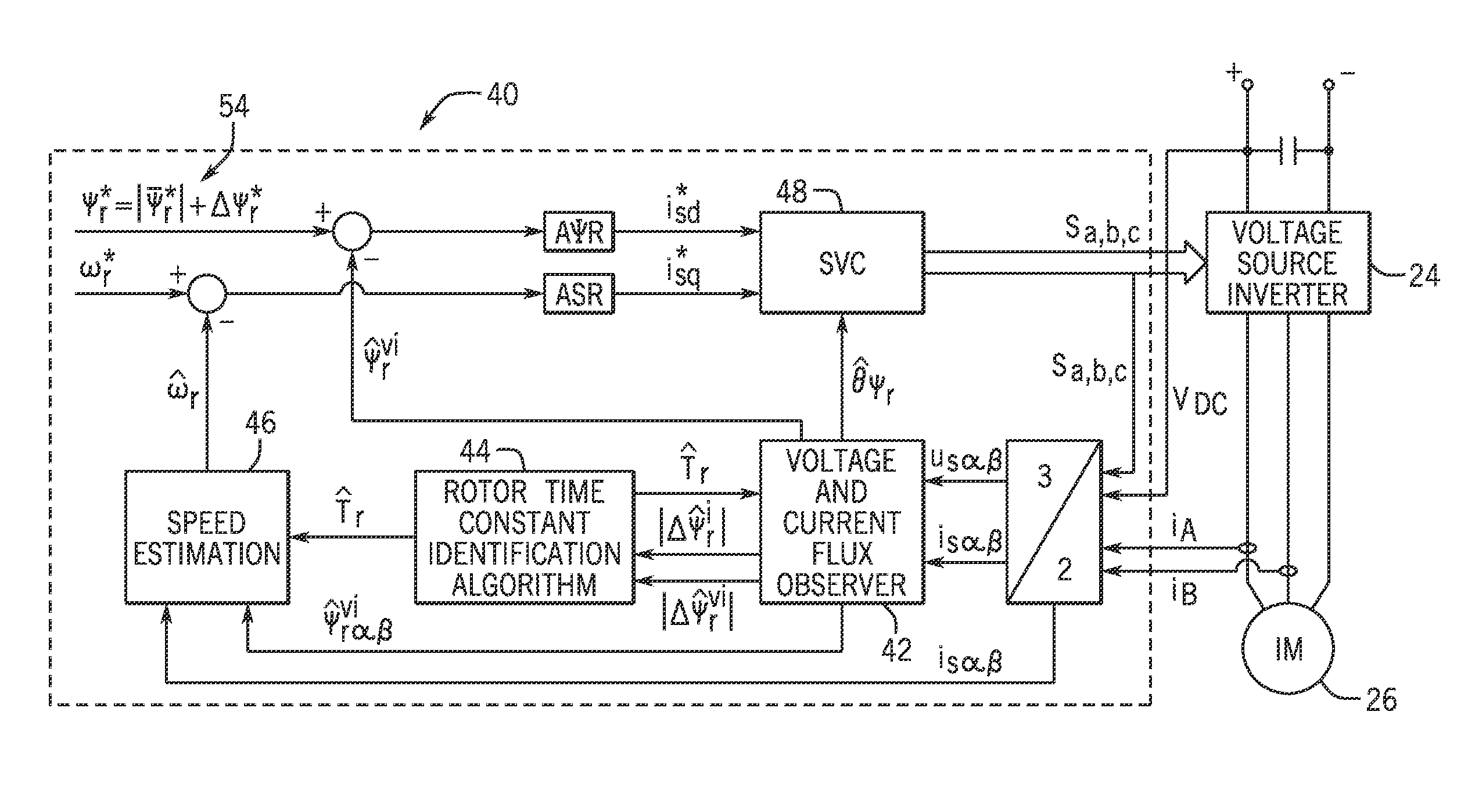
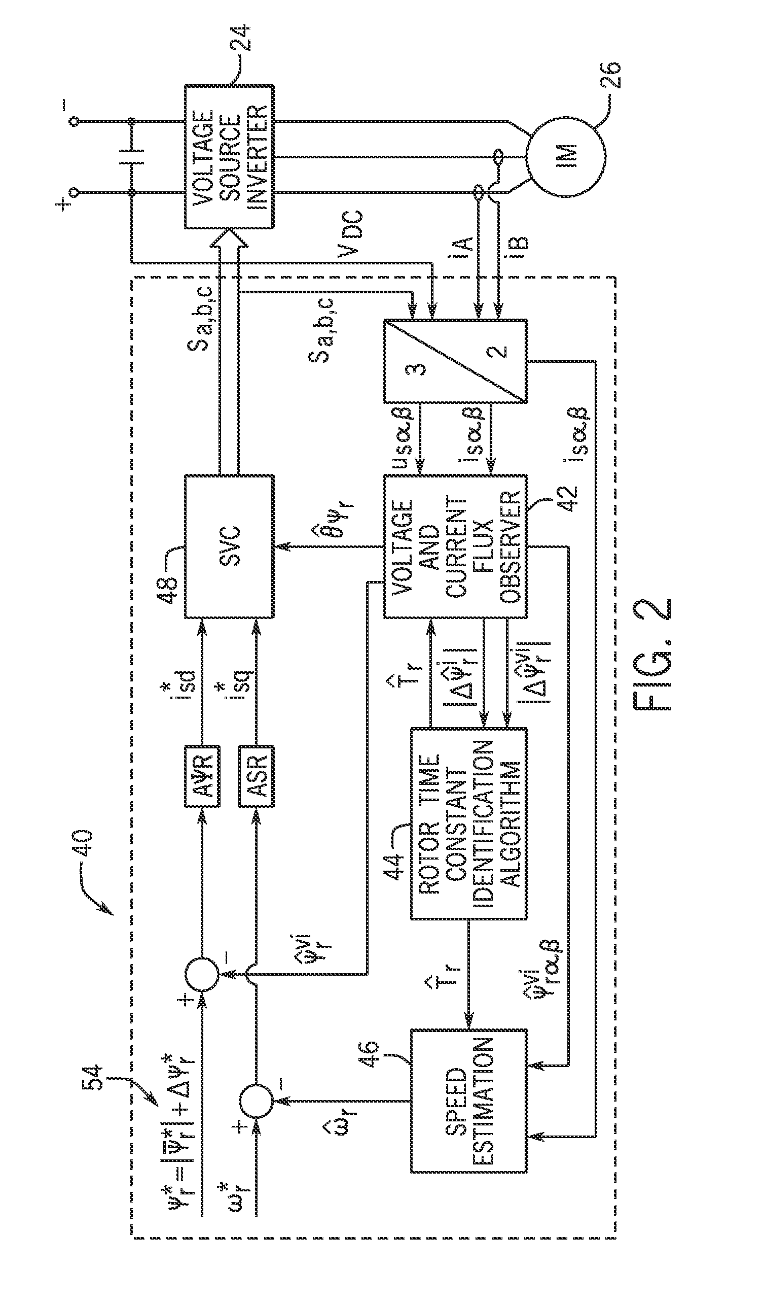
[0020]Embodiments of the invention are directed to a system and method that provides for the simultaneous estimation of the rotor speed and rotor time constant in an AC induction machine. According to embodiments of the invention, the estimation of the rotor speed and rotor time constant for the AC induction machine may be performed by any of a number of digital signal processing (DSP) devices, with such devices being either integrated into a motor drive associated with the induction machine or being provided as stand-alone algorithm unit and / or processing / computing device.

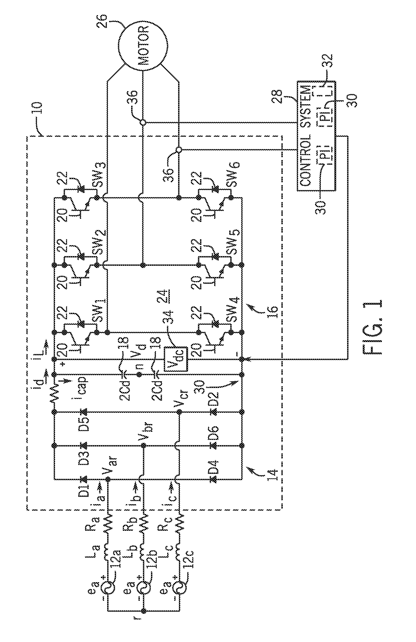
[0021]Referring to FIG. 1, the general structure of a motor drive 10 configured to control operation of an associated AC induction machine is shown that is useable with embodiments of the invention.

[0022]The motor drive 10 may be configured, for example, as a variable speed drive (VSD) designed to receive a three AC power input, rectify the AC input, and perform a DC / AC conversion of the rectified segment into a t...


PUM


Abstract

A system and method for determining a rotor time constant of an AC induction machine is disclosed. During operation of the induction motor, a flux signal is injected into a rotor flux command so as to generate a time-variant rotor flux. A voltage-current flux observer determines amplitudes of rotor flux variations resulting from the time-variant rotor flux, with the amplitudes of the rotor flux variations comprising an amplitude of a rotor flux variation based on a current model of the voltage-current flux observer and an amplitude of a rotor flux variation based on a combined voltage-current model of the voltage-current flux observer. A rotor time constant of the induction motor is then estimated based on the determined amplitudes of the rotor flux variations.

Description

BACKGROUND OF THE INVENTION[0001]The present invention relates generally to AC induction machines and, more particularly, to a system and method for determining a rotor time constant of an AC induction machine.[0002]Electric motors, such as AC induction motors, consume a large percentage of generated electricity capacity. Many applications for this “workhorse” of industry are fan and pump industrial applications. For example, in a typical integrated paper mill, low voltage and medium voltage motors may comprise nearly 70% of all driven electrical loads. Due to the prevalence of these motors in industry, it is paramount that the electric motors be operated reliably and efficiently. Motor design parameters and performance parameters are often required by motor management systems to optimize the control and operations of electric motors. Similarly, motor status monitoring enables the electric motors to operate reliably, and many motor status monitoring techniques look for certain motor...

Claims


Application Information

Patent Timeline
Patent Type & Authority Patents(United States)
IPC IPC(8): H02P23/00H02P21/14
CPCH02P21/145H02P21/13H02P21/16H02P21/08
Inventor WANG, KAIYAO, WENXILI, HUAQIANGLU, ZHENGYU
Owner EATON INTELLIGENT POWER LTD
Why Eureka
Try Eureka