
Systems, methods, and apparatus for regenerating a catalytic material

a technology of catalytic material and apparatus, which is applied in the direction of emissions prevention, combustion types, separation processes, etc., can solve the problems of insufficient compliance with the increased standards, no/sub>x/sub>that is present in the flue gas may be reduced to nitrogen and water with great difficulty, and achieves the effect of facilitating the reduction of reducing an amount of nox

Active Publication Date: 2015-06-23
GENERAL ELECTRIC CO
View PDF48 Cites 2 Cited by
  • Summary
  • Abstract
  • Description
  • Claims
  • Application Information

AI Technical Summary

Benefits of technology

The patent describes a system that reduces the amount of nitrogen oxides (NOx) in exhaust gases produced by a gas turbine engine. The system includes a heat recovery steam generator (HRSG) with a heating device and an oxidation catalyst. The heating device heats the exhaust gases before they enter the oxidation catalyst. The oxidation catalyst then breaks down the NOx into harmless nitrogen gas (N2) and water vapor (H2O) at a specific temperature. This simultaneously regenerates the catalyst, which reduces NOx in the exhaust gases. The result is cleaner exhaust emissions from the gas turbine engine.

Problems solved by technology

Oxides of nitrogen include nitric oxide (NO) and nitrogen dioxide (NO2), which is known to produce a visible yellow plume from exhaust stacks and that is alleged to contribute to the creation of “acid rain.” However, known combustion controls may provide only limited emissions control and may prove inadequate in satisfying the increased standards and the often-conflicting goals, such that further improvements of post-combustion exhaust gas treatment systems are desirable.
Thus, NOx that is present in the flue gas may be reduced to nitrogen and water with great difficulty.
However, the reaction rate over the catalyst is dependent on the inlet gas temperature as such the rate of NOx destruction is insufficient until the flue gas is heated to the suitable temperature.
However, NO is less soluble than NO2 and other NxOy compounds in such solutions.
However, sulfur dioxides (SOx) and other contaminants can foul the oxidation catalyst over time, which reduces the NO oxidation yield.

Method used


Image

  • Systems, methods, and apparatus for regenerating a catalytic material
  • Systems, methods, and apparatus for regenerating a catalytic material
  • Systems, methods, and apparatus for regenerating a catalytic material

Examples


Embodiment Construction

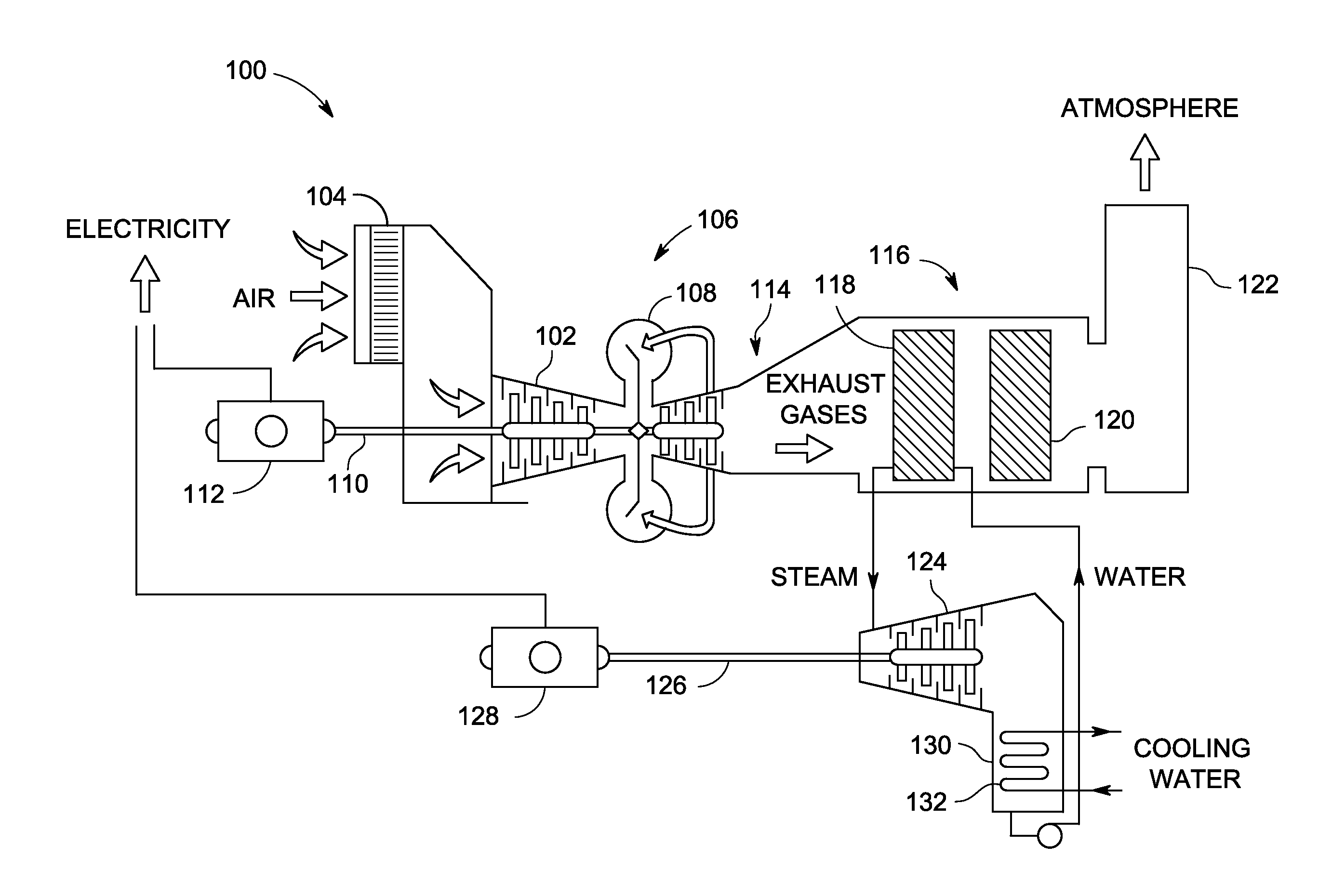
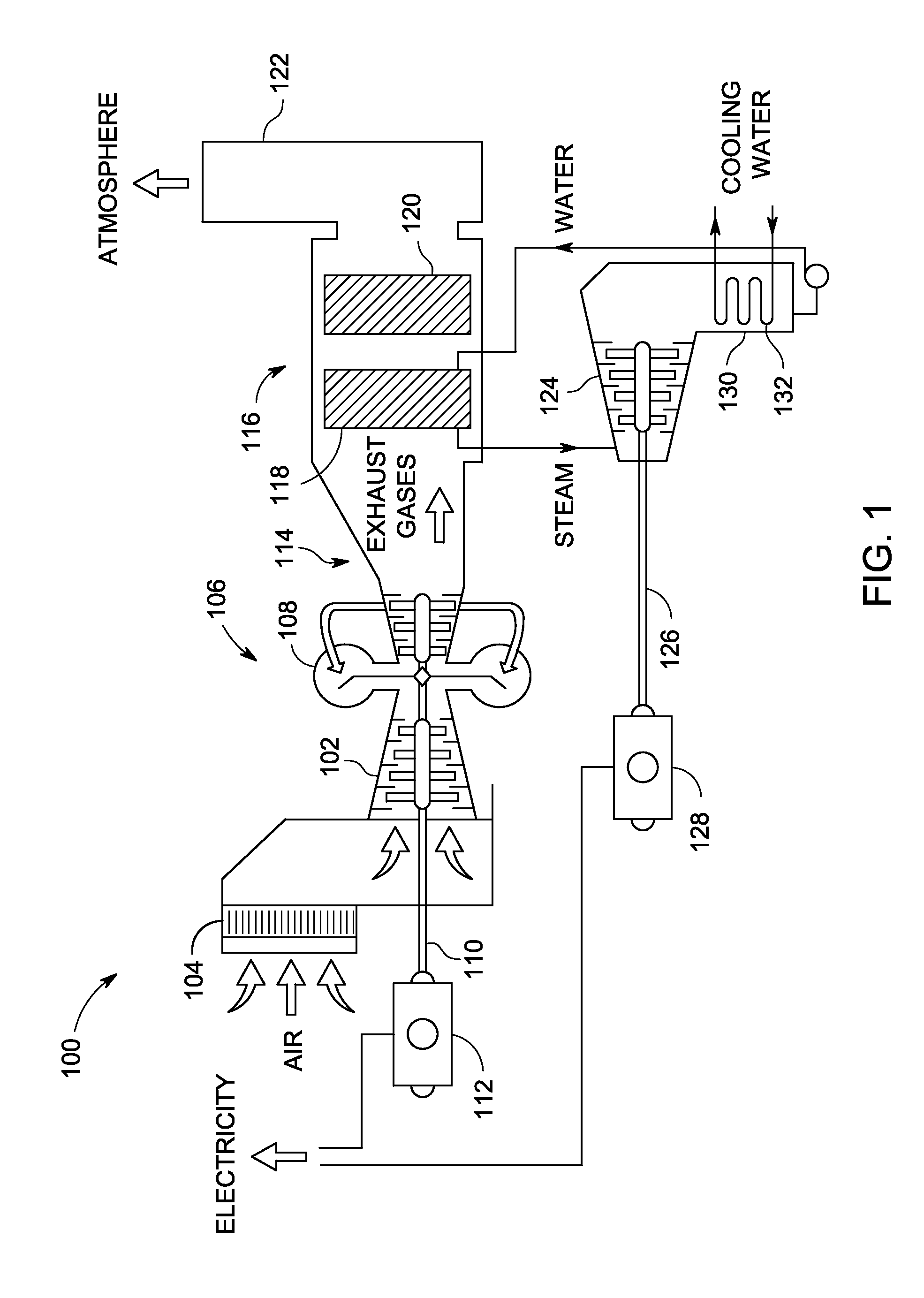
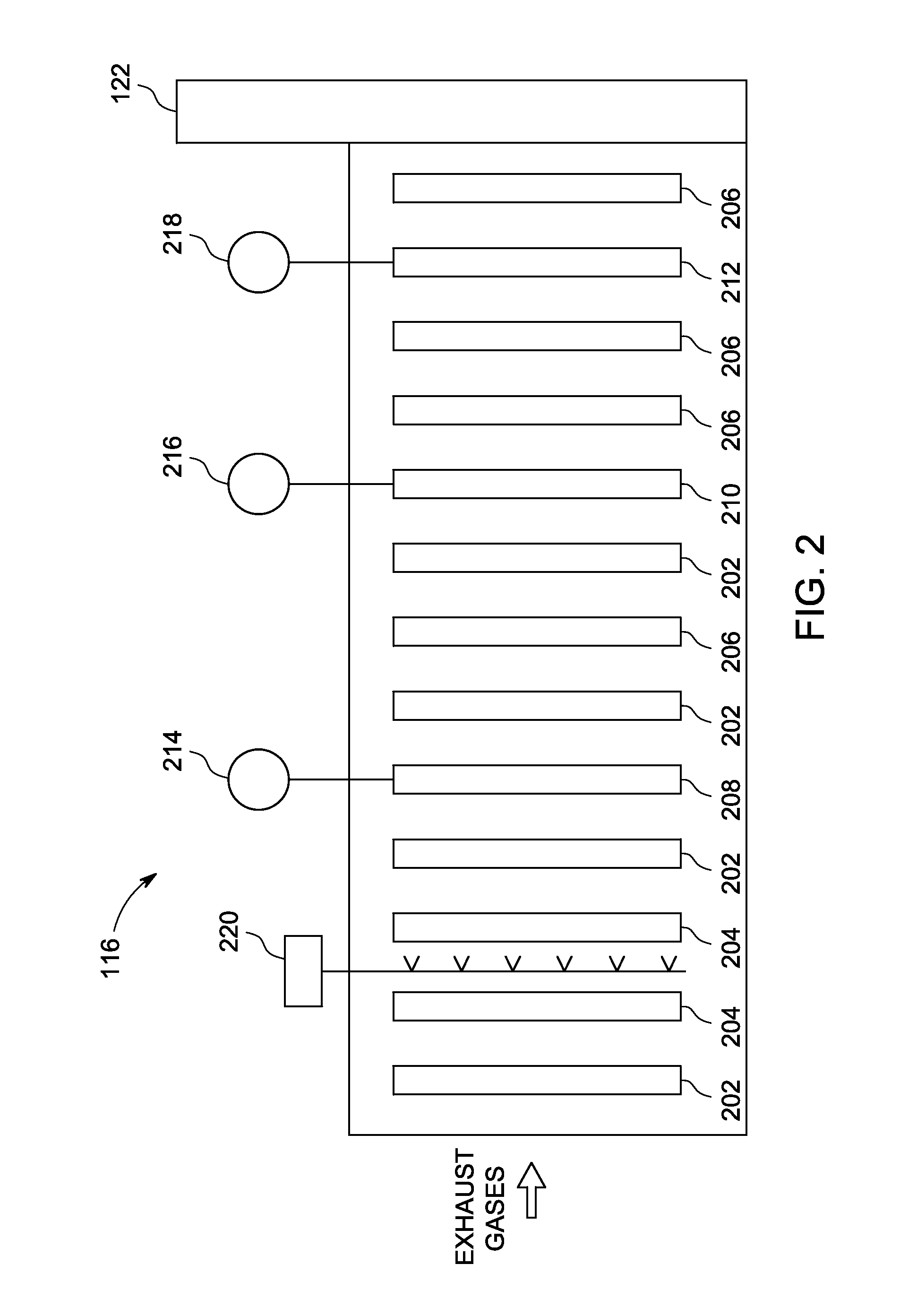
[0014]FIG. 1 a simplified schematic diagram of an exemplary combined cycle power plant 100. In the exemplary embodiment, power plant 100 includes a compressor 102 including an air intake 104 that receives air. Compressor 102 is coupled to a gas turbine engine 106 that includes one or more combustion chambers 108. Compressor 102 compresses air received via air intake 104 and channels the compressed air into combustion chambers 108, wherein the compressed air is mixed with fuel and ignited to supply gas turbine engine 106 with hot combustion gases for driving a first shaft 110. First shaft 110 is coupled to a first generator 112, and causes first generator 112 to generate electricity. Moreover, gas turbine engine 106 discharges exhaust gases into an exhaust duct 114, including, for example and not by way of limitation, oxides of nitrogen (NOx), carbon monoxide (CO), and unburned hydrocarbons.

[0015]In the exemplary embodiment, power plant 100 also includes a heat recovery steam generat...


PUM

PropertyMeasurementUnit
temperatureaaaaaaaaaa

Abstract

A steam generator coupled in flow communication downstream from a combustion device that produces a flow of exhaust gases includes a heating device configured to heat the exhaust gases that include oxides of nitrogen (NOx), and an oxidation catalyst coupled downstream from the heating device. The oxidation catalyst facilitates reducing an amount of NOx in the exhaust gases channeled into the oxidation catalyst at a first temperature that is less than a thermal regeneration temperature for a catalytic material and at a second temperature that is approximately equal to at least the thermal regeneration temperature such that the catalytic material is simultaneously regenerated.

Description

BACKGROUND OF THE INVENTION[0001]The embodiments described herein relate generally to emissions treatment systems and, more particularly, to a heat recovery steam generator for use in reducing NO2 formation in the exhaust path of a combustion system and for regenerating a catalytic material that facilitates the reduction in NO2 formation.[0002]During the combustion of natural gas and liquid fuels, pollutants such as, but not limited to, carbon monoxide (CO), unburned hydrocarbons (UHC), and oxides of nitrogen (NOx) emissions, may be formed and / or emitted into an ambient atmosphere. In general, CO and UHC may be formed during combustion conditions at lower temperatures and / or during combustion conditions when an insufficient amount of time to complete a reaction is available. In contrast, NOx is generally formed during combustion conditions at higher temperatures. At least some known pollutant emission sources include industrial boilers and furnaces, reciprocating engines, gas turbin...

Claims


Application Information

Patent Timeline
Patent Type & Authority Patents(United States)
IPC IPC(8): F01K23/10F01K17/02F23G7/07F23J15/02F23J15/08
CPCF01K23/10F01K17/02F23G7/07F23J15/02F23J15/08F23J2215/10Y02E20/12Y02E20/16
Inventor KRAEMER, GILBERT OTTO
Owner GENERAL ELECTRIC CO
Learn More