3-coil wireless power transfer system for eye implants

a technology of power transfer system and eye implant, which is applied in the field of three coils of wireless power transfer system, can solve the problems of consuming more than 100 milliwatts (mw), and limiting the usefulness of high-resolution sensors and processors. achieve the effect of increasing power transfer efficiency

Active Publication Date: 2015-07-14
UNIV OF SOUTHERN CALIFORNIA +1
View PDF14 Cites 7 Cited by
  • Summary
  • Abstract
  • Description
  • Claims
  • Application Information

AI Technical Summary

Benefits of technology

[0014]Generally, a third coil, called a “buffer coil,” is introduced between the transmitter coil and receiver coil to increase power transfer efficiency between the transmitter coil and receiver coil. In particular with the physical constraints of the human eye, an intervening buffer coil fits into the available spaces well. In some instances, it may not need to be surgically implanted at all, but instead worn by a patient as a sclera lens.
[0015]The buffer coil and / or receiver coil can be geometrically oblong, such as an oval, in order to account for greater movement of the eye in the horizontal direction as opposed to the vertical direction.
[0017]Electrical resistance caused by the skin effect can be minimized by sizing the electrical traces appropriately for the electromagnetic induction frequency. Further, the traces can be layed out so when they are wound into the coil, the traces shift their axial positions so as to share the (axial) outside positions, thus minimizing resistance caused by the proximity effect. The traces can shift axial positions by having an outermost trace pass over a fold line (i.e., a crease) while an inner trace takes its place at the outermost position.
[0018]Because silicon wafer substrates can be small, a U-shaped section of traces can effectively double the length of the traces to be coiled into a coil. Multiple U-shaped sections can triple, quadruple, etc. the length of the traces. Folding the U-shaped region up and then folding the two sides of the U together results in the traces that were once adjacent on the substrate being disposed in opposite directions from one another.
[0026]Some embodiments relate to a method of efficiently receiving power inside an eye for an intraocular electronic device without an sclera-piercing cable. The method includes receiving, into a buffer coil affixed external to a sclera of an eye, a varying magnetic field by way of a first electromagnetic induction, the varying magnetic field causing current in the buffer coil, inducing current, within a receiver coil within the eye, by way of a second electromagnetic induction from the current in the buffer coil to the receiver coil, and powering an intraocular electronic device using the induced current from the receiver coil.
[0030]The method can include sealing air within a chamber, and rigidly attaching the chamber to the coil, thereby adding buoyancy to the coil.

Problems solved by technology

Unfortunately, the high-resolution sensors and processors have relatively high power consumption, for example, greater than 100 milliwatts (mW).
Current battery technology limits their usefulness for such implants, so power is preferably drawn from outside the body.
However, because of the extremely demanding physical constraints in and around the eye, the physical placement of the implanted receiver coil remains a matter of ongoing debate.
There are tradeoffs between the power-transfer capability, surgical risk and long-term implantation.
While there are fewer constraints on a transmitting coil, which is outside the body, it cannot be too powerful lest it heat the receiver coil too much or subject the patient to unacceptable levels of electromagnetic fields.
This trans-sclera, trans-choroid cable potentially causes infection and hypotony in the long-term implantation.
However, with a 25 millimeter (mm) (1-inch) separation between the transmitter and receiver coils, this 2-coil configuration suffers low efficiency (e.g., 7%) from the limited Q of the receiver coil and the small coupling coefficient k between the coupled coils.

Method used


Image

  • 3-coil wireless power transfer system for eye implants
  • 3-coil wireless power transfer system for eye implants
  • 3-coil wireless power transfer system for eye implants

Examples


Embodiment Construction

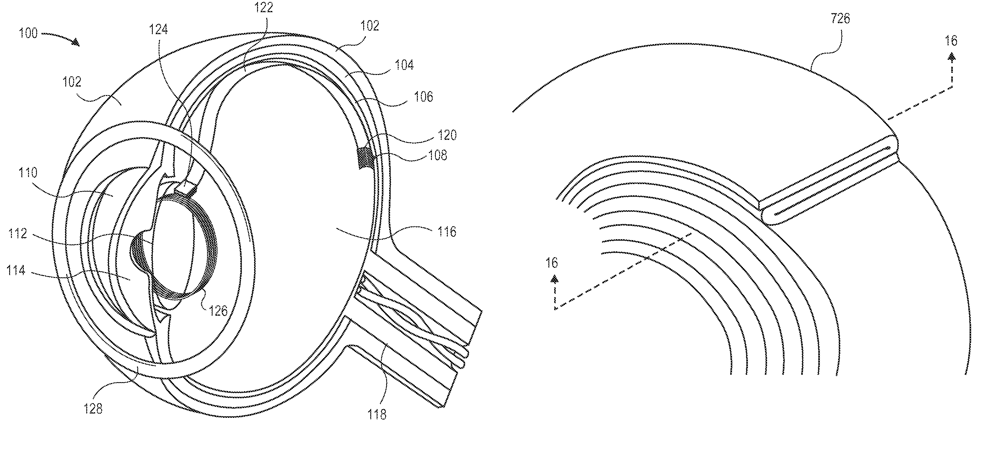
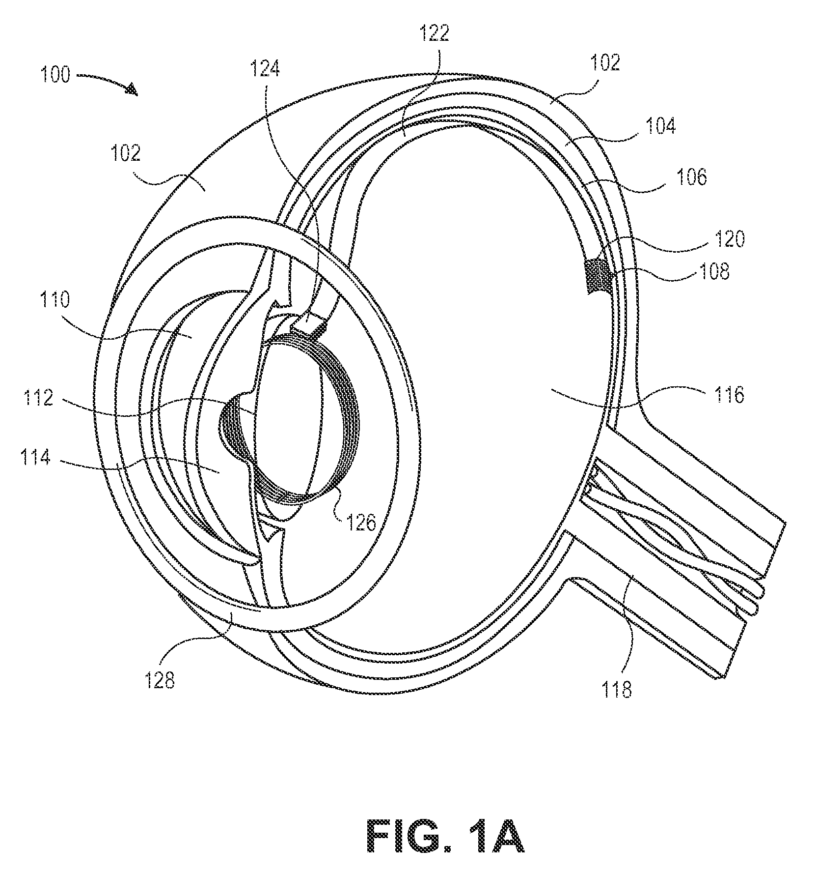
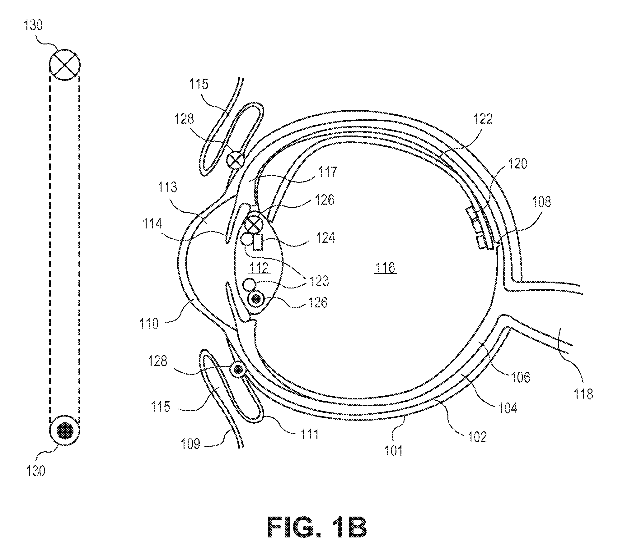
[0074]A three-coil power transmission system for implanted devices offers many technical benefits. The third, buffer coil increases efficiency of power transmission between the transmitter coil and receiver coil. It also allows another set of design parameters with which to work so that a receiver coil (or transmitter coil) may be sized for small, constrained spaces. A three-coil structure can tolerate larger misalignments in the X-Y plane between coils than a two-coil structure. This can be important for cases in which the receiver coil is buried in the body and not visible, so an exact determination of its location is unknown. It can also help mitigate voluntary or involuntary movements of a subject, keeping efficiency high. Further, a three-coil structure can tolerate larger angular misalignments between coils than a two-coil structure. The coils do not need to be aligned as much. This may be especially important with blind people who cannot fixate their eyes in a certain positio...


PUM

PropertyMeasurementUnit
power consumptionaaaaaaaaaa
outer diameteraaaaaaaaaa

Abstract

A three-coil electromagnetic induction power transfer system is disclosed for epiretinal prostheses and other implants. A third, buffer coil is disposed between an external transmitting coil and a receiver coil buried within the body to improve efficiency and robustness to misalignments. One or more of the coils can be manufactured using micromechanical machining techniques to lay out conductors in a ribbon of biocompatible insulator, folding lengths of the insulated conductor traces longitudinally over one another, and then spiraling them into a ring. The traces change axial position in the ring by shifting across fold lines. One or more U-shaped sections on the traces can be folded so that adjacent traces can project opposite one another, lengthening the resulting ribbon that can be wound into a coil.

Description

CROSS-REFERENCES TO RELATED APPLICATIONS[0001]This application claims the benefit of U.S. Provisional Application No. 61 / 692,138, filed Aug. 22, 2012, which is hereby incorporated by reference in its entirety for all purposes.STATEMENT AS TO RIGHTS TO INVENTIONS MADE UNDER FEDERALLY SPONSORED RESEARCH AND DEVELOPMENT[0002]This invention was made with government support under EEC0310723 awarded by the National Science Foundation. The government has certain rights in the invention.BACKGROUND[0003]1. Field of the Art[0004]Embodiments of the present invention generally relate to wireless power transfer to surgically implanted prostheses, in particular, to a three-coil power transfer system with one of the coils being a fully intraocular coil.[0005]2. Description of the Related Art[0006]Age-related macular degeneration (AMD) and retinitis pigmentosa (RP) are two most common outer-retina degenerative diseases of the human eye. There is promise in the use of retinal prostheses in order to ...

Claims


Application Information

Patent Timeline
Patent Type & Authority Patents(United States)
IPC IPC(8): A61F2/14A61N1/36A61N1/378A61N1/05
CPCA61F2/14A61N1/36046A61N1/3787A61N1/0543A61N1/0529A61N1/0551A61N1/3605A61F2250/0001A61F9/007C23F1/00H01F27/2804H01F2027/2809
Inventor TAI, YU-CHONGZHAO, YUHUMAYUN, MARKWEILAND, JAMES D.
Owner UNIV OF SOUTHERN CALIFORNIA
Why Eureka
Try Eureka