WDM telecommunications link with coherent detection and optical frequency comb sources

a technology of optical frequency comb and telecommunications link, which is applied in the field of optical link combining, can solve the problems of phase and frequency lock, difficulty in realization, and mode locking of comb components, and achieve the effect of facilitating the demodulation of a large number of coherently detected optical channels and reducing the frequency of residual intermediate frequencies

a technology of optical frequency comb and telecommunications link, which is applied in the field of optical link combining, can solve the problems of phase and frequency lock, difficulty in realization, and mode locking of comb components, and achieve the effect of facilitating the demodulation of a large number of coherently detected optical channels and reducing the frequency of residual intermediate frequencies

US9088371B2Active Publication Date: 2015-07-21RWTH AACHEN UNIV

Image

  • WDM telecommunications link with coherent detection and optical frequency comb sources
  • WDM telecommunications link with coherent detection and optical frequency comb sources
  • WDM telecommunications link with coherent detection and optical frequency comb sources

Examples


Embodiment Construction

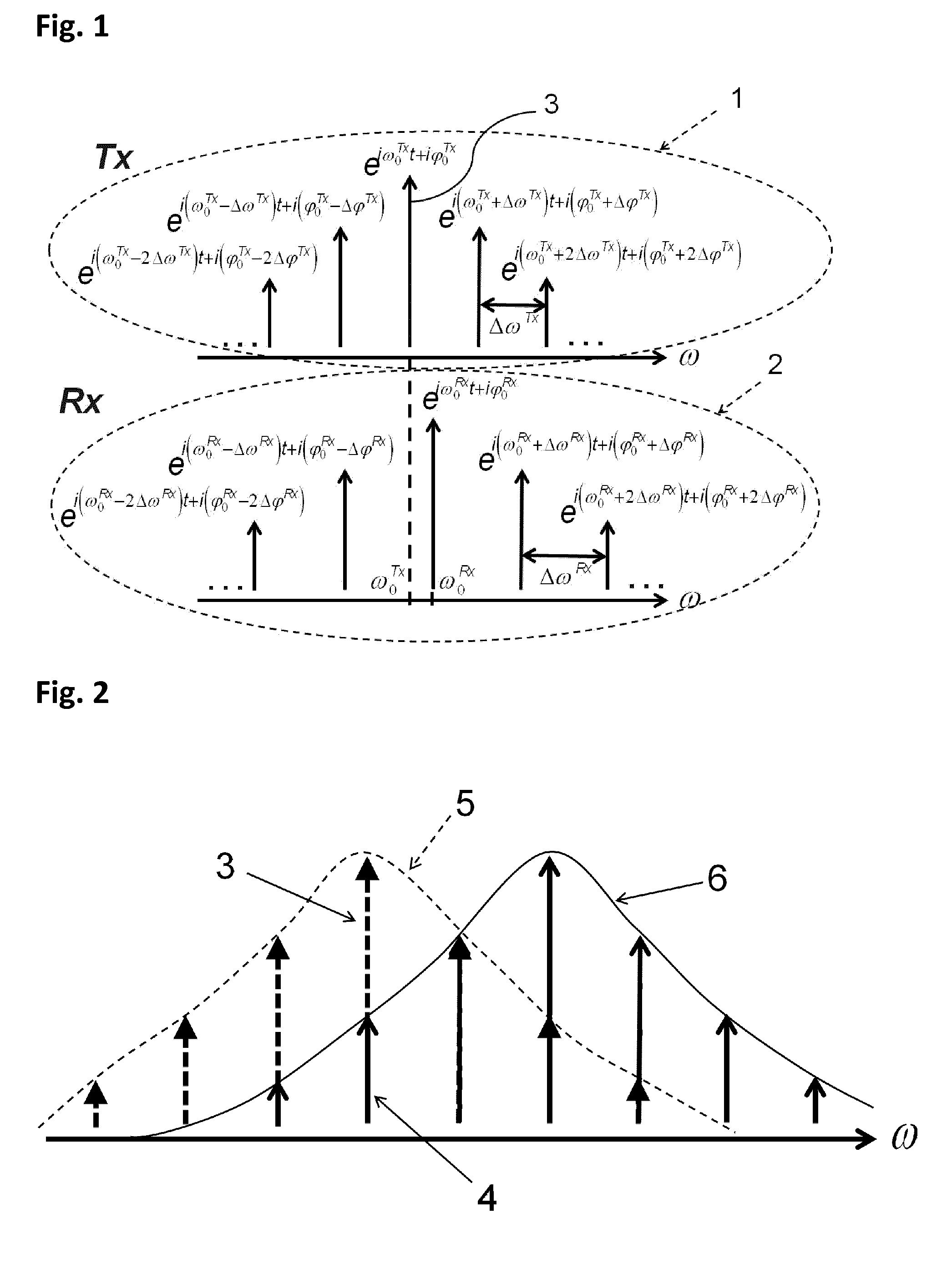
[0079]In FIG. 1, a transmitter Tx mode-locked frequency comb spectrum 1 and a receiver Rx mode-locked frequency comb spectrum 2 are shown. A frequency comb component 3 of the transmitter Tx frequency comb has a frequency ω0Tx and a phase φ0Tx. The transmitter Tx comb has a free spectral range (also called frequency offset of the transmitter comb) ΔωTx and a phase offset ΔφTx. Similar notation hold for the receiver Rx comb. The vertical axis represents the power level of the frequency comb components. The difference between the frequencies of the frequency comb components of index 0 of the two combs is illustrated.

[0080]In FIG. 2 the frequency comb components 3 of the transmitter Tx comb are represented with one type of arrow (dashed, filled arrow tip) and, frequency components 4 of the receiver Rx comb are represented with another type of arrow (continuous). As shown, the two combs are locked to each other, but the envelope functions 5 and 6 of the transmitter Tx and receiver Rx com...


PUM


Abstract

An optical data link has a transmitter and a receiver with coherent detection at the receiver and more than one optical carrier frequency. The optical carrier frequencies are generated by a frequency comb source in both the transmitter and the receiver. The frequency comb sources generate frequency combs that have frequency components and a free spectral range. The optical carrier frequencies transport more than one optical channel. Either at least one frequency component or the free spectral range of the optical comb generated at the receiver is locked to the comb generated at the transmitter by an optical phase locked loop, or an electrical phase locked loop or a feed-forward carrier recovery generates an intermediate frequency carrier reference that is routed to more than one channel to demodulate the data.

Description

CROSS-REFERENCE TO RELATED APPLICATIONS[0001]This application is the U.S. National Phase of International Application No. PCT / EP2012 / 057829, filed Apr. 27, 2012, claiming benefit of U.S. Provisional Patent Application No. 61 / 481,159, filed Apr. 30, 2011, the contents of which are hereby incorporated by reference in their entirety as part of the present disclosure.FIELD OF THE INVENTION[0002]The present invention relates to an optical link combining wavelength domain multiplexing (WDM) with coherent detection.BACKGROUND OF THE INVENTION[0003]An optical frequency comb is light with an optical spectrum consisting of multiple discrete frequency components. The frequency difference between adjacent frequency components is substantially constant and called the frequency offset. The phase difference between adjacent frequency components is substantially constant and called the phase offset. In other words, individual frequency components are described by exp(i×ωjt+φj) where i is the index ...

Claims


Application Information

Patent Timeline
21 Jul 2015
Publication
US9088371B2
IPC
H04B10/61; H04J14/02; H04J14/00; H04B10/64
CPC
H04B10/6164; H04B10/64; H04J14/002; H04J14/02
Inventors
WITZENS, JEREMY