
Quantum dot solar cells with band alignment engineering

a solar cell and band alignment technology, applied in the field of solar cells, can solve the problems of poor air stability, increase manufacturing complexity and cost, and achieve the effect of facilitating hole extraction and facilitating hole extraction

Active Publication Date: 2015-08-04
MASSACHUSETTS INST OF TECH
View PDF4 Cites 20 Cited by
  • Summary
  • Abstract
  • Description
  • Claims
  • Application Information

AI Technical Summary

Benefits of technology

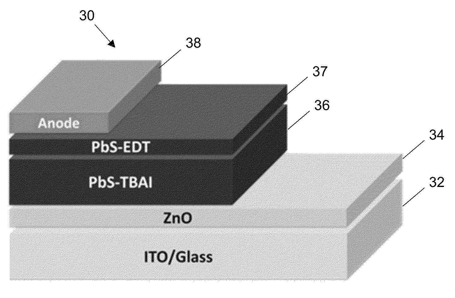
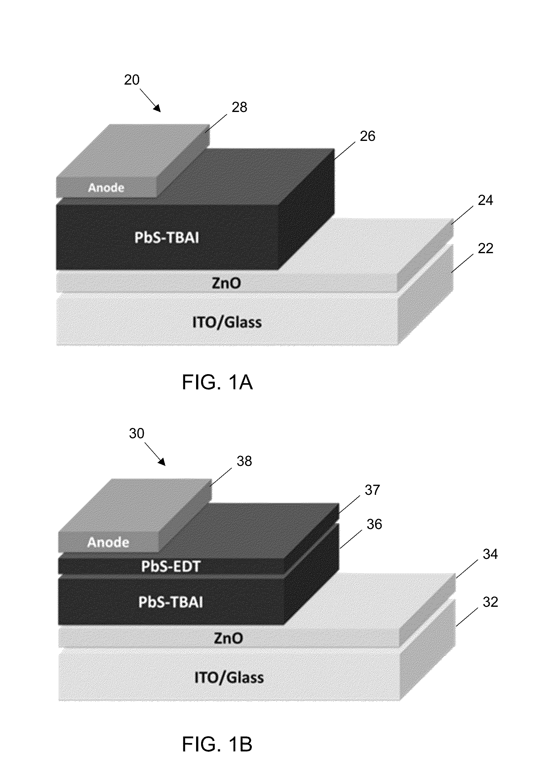
The patent describes a solar cell and a method of making it. The solar cell has a unique structure with an acceptor layer, donor layer, and blocking layer. The blocking layer is designed to partially block electron flow and facilitate hole extraction. The donor layer is treated with a first quantum dot ligand, while the accepting layer is treated with a second quantum dot ligand. The anode and cathode may include materials such as Indium doped tin oxide, Fluorine-doped tin oxide, or Aluminum-doped zinc oxide. The method involves solution processing at room temperature and may involve thermal treatment afterward. The blocking layer may be made of PbS quantum dots, while the donor layer may be made of a PbS QD film treated with TBAI or a Halide-treated lead chalcogenide quantum dot. The technical effects of this structure and method include improved photovoltaic performance and stability.

Problems solved by technology

However, solar cells based on solution-processed organic, inorganic, and hybrid materials reported thus far generally suffer from poor air stability, require an inert-atmosphere processing environment, or necessitate high temperature processing, all of which increase manufacturing complexities and costs.
Simultaneously fulfilling the goals of high efficiency, low-temperature fabrication conditions, and good atmospheric stability remains a major technical challenge.

Method used


Image

  • Quantum dot solar cells with band alignment engineering
  • Quantum dot solar cells with band alignment engineering
  • Quantum dot solar cells with band alignment engineering

Examples


Embodiment Construction

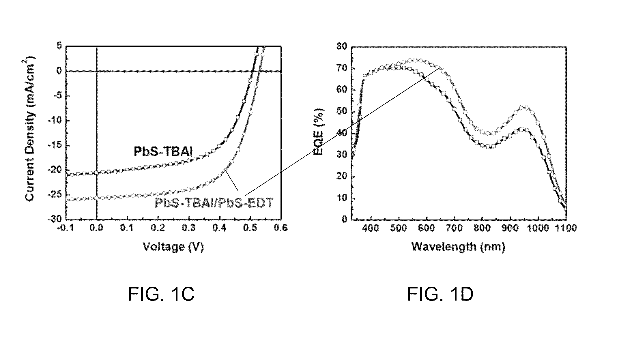
[0031]Disclosed herein are quantum dot (QD) solar cells that can be fabricated using solution processing. Such solar cells fulfill the goals of high efficiency, low-temperature fabrication conditions, and good atmospheric stability. For example, QD solar cells may be fabricated using room-temperature solution-processed ZnO / PbS. By engineering the band alignment of the QD layers through the use of different ligand treatments, a certified efficiency of 8.55% has been reached. Furthermore, the performance of unencapsulated devices remains unchanged for over 150 days of storage in air. This material system introduces a new approach towards the goal of high-performance air-stable solar cells compatible with simple solution processes and deposition on flexible substrates.

[0032]Near-infrared PbS QDs composed of earth-abundant elements are promising candidates for photovoltaic applications because of a tunable energy bandgap that covers the optimal bandgap range for single and multi-junctio...


PUM


Abstract

A solar cell and method of making are disclosed. The solar cell includes an acceptor layer a donor layer treated with a first quantum dot (QD) ligand and a blocking layer treated with a second, different, QD ligand. The acceptor layer has an acceptor layer valence band and an acceptor layer conduction band. The donor layer has a donor layer valence band and a donor layer conduction band, the donor layer valence band is higher than the acceptor layer valence band, the donor layer conduction band is higher than the acceptor layer conduction band. The blocking layer least partially blocks electron flow in at least one direction, the blocking layer having a blocking layer valence band and a blocking layer conduction band, the blocking layer valence band is higher than the donor layer valence band, the blocking layer conduction band is higher than the donor layer conduction band.

Description

FIELD OF THE INVENTION[0001]The present disclosure generally relates to solar cells and in more particular to quantum dot solar cells with band alignment engineering.BACKGROUND[0002]Solution processing is a promising route for the realization of low-cost, large-area, flexible, and light-weight photovoltaic devices with short energy payback time and high specific power. However, solar cells based on solution-processed organic, inorganic, and hybrid materials reported thus far generally suffer from poor air stability, require an inert-atmosphere processing environment, or necessitate high temperature processing, all of which increase manufacturing complexities and costs. Simultaneously fulfilling the goals of high efficiency, low-temperature fabrication conditions, and good atmospheric stability remains a major technical challenge.SUMMARY OF THE INVENTION[0003]A solar cell and method of making are disclosed. The solar cell includes an acceptor layer a donor layer treated with a first ...

Claims


Application Information

Patent Timeline
Patent Type & Authority Patents(United States)
IPC IPC(8): H01L29/06H01L51/42H01L31/0352H01L31/00H01L31/0272
CPCH01L31/0272H01L51/428H01L51/4206H01L31/035209Y02E10/549Y02P70/50H10K30/35H10K30/353H10K30/50H10K30/451H10K30/65
Inventor CHUANG, CHIA-HAO MARCUSBULOVIC, VLADIMIRBAWENDI, MOUNGI G.BROWN, PATRICK RICHARD
Owner MASSACHUSETTS INST OF TECH
Learn More