Systems and methods for enhanced accuracy in OCT imaging of the cornea

a technology of oct imaging and enhanced accuracy, applied in the field of medical imaging, can solve the problems of data being more susceptible to eye motion, longer scan time, and limited accuracy of oct for a number of ophthalmic applications, and achieve the effect of enhancing the accuracy in the calculation of ocular measurements

Active Publication Date: 2015-08-11
CARL ZEISS MEDITEC INC
View PDF39 Cites 7 Cited by
  • Summary
  • Abstract
  • Description
  • Claims
  • Application Information

AI Technical Summary

Benefits of technology

[0017]Here we propose several approaches for enhancing the accuracy in the calculation of ocular measurements, including anterior segment measurements such as corneal surface modeling, pachymetry maps, keratometric value

Problems solved by technology

Even with the increased speed of FD-OCT, however, the accuracy of OCT for a number of ophthalmic applications can be limited by the effect of motion during data acquisition.
However, denser sampling would require a longer scan time, and would, in turn, make the data more susceptible to eye motion.
Corneal topography, however, has certain limitations.
Also, error can arise from problems caused by misalignment and fixation error that amplify measurements of astigmatism, which decreases the accuracy of the corneal measurements.
It can also be difficult to calculate the position of the center from the small central rings, and there can be increased inaccuracy toward the periphery because the accuracy of each point depends on the accuracy of all preceding points.
This assumption of a fixed ratio leads often to incorrect results when changes in surface curvature occur mostly at the anterior corneal surface—for instance, due to pathology or refractive surgery.
This assumption can thus lead to incorrect corneal power determinations (M. Tang et al.
One of the biggest challenges, however, in using OCT B-scans for calculating the corneal power is the error in curvature measurements caused by motion of the cornea in the z and transverse directions.
Small movements can cause significant errors in power calculations.
For example, a z displacement of 1.3 μm while the scan beam moves 1 mm from the vertex will result in error

Method used


Image

  • Systems and methods for enhanced accuracy in OCT imaging of the cornea
  • Systems and methods for enhanced accuracy in OCT imaging of the cornea
  • Systems and methods for enhanced accuracy in OCT imaging of the cornea

Examples


Embodiment Construction

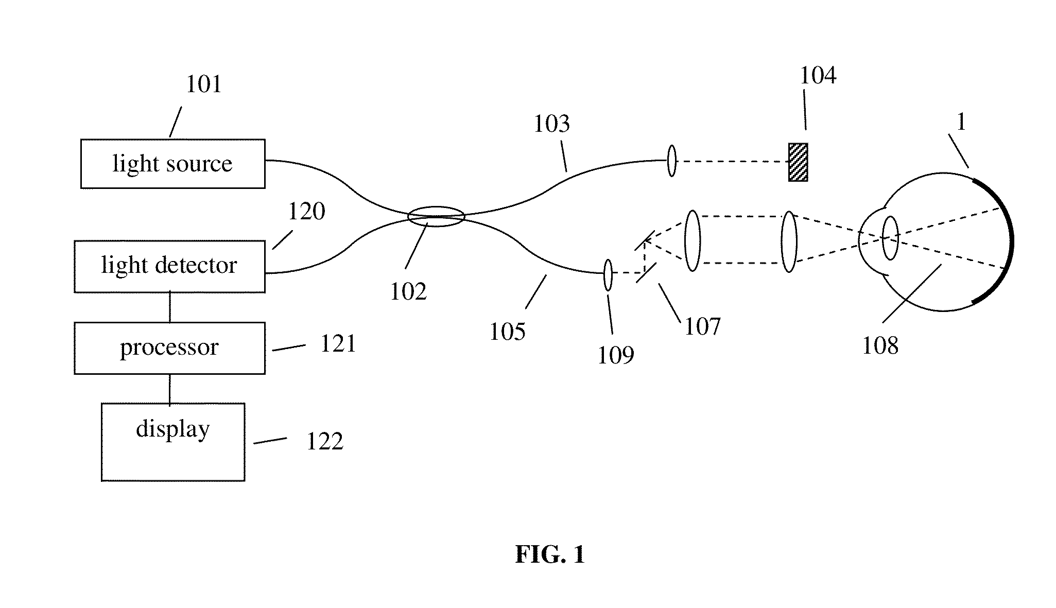
[0038]A diagram of a generalized frequency-domain OCT (FD-OCT) system for use in ophthalmology is shown in FIG. 1. Light from source 101 is routed, typically by optical fiber 105, to illuminate the sample 110, a typical sample being tissue in the human eye. Typical sources are a broadband light source with short temporal coherence length in the case of spectral-domain OCT (SD-OCT), or a wavelength-tunable laser source in the case of swept-source OCT (SS-OCT). The beam of light (dashed line 108) is scanned laterally (in x and y, if z is parallel to the beam of light) over the area or volume to be imaged, typically with scanning optics 107 between the output of the fiber and the sample. Light backreflected from the sample returns through scanning optics 107 and is collected, typically into the same fiber 105 used to route the light for sample illumination. Lens 109 is used to collimate the illuminating light exiting the fiber and to focus the reflected light back into the fiber for co...


PUM


Abstract

Systems and methods for enhanced accuracy in optical coherence tomography imaging of the cornea are presented, including approaches for more accurate corneal surface modeling, pachymetry maps, keratometric values, and corneal power. These methods involve new scan patterns, an eye tracking mechanism for transverse motion feedback, and advanced motion correction algorithms. In one embodiment the methods comprise acquiring a first sparse set of data, using that data to create a corneal surface model, and then using the model to register a second set of denser data acquisition. This second set of data is used to create a more accurate, motion-corrected model of the cornea, from which pachymetry maps, keratometric values, and corneal power information can be generated. In addition, methods are presented for determining simulated keratometry values from optical coherence tomography data, and for better tracking and registration by using both rotation about three axes and the corneal apex.

Description

PRIORITY[0001]This application claims the benefit of the filing date under 35 U.S.C. §119(e) of Provisional U.S. Patent Application Ser. No. 61 / 588,565, filed on Jan. 19, 2012, which is hereby incorporated by reference in its entirety.FIELD OF THE INVENTION[0002]The present invention relates to medical imaging, and in particular data acquisition and processing methods for data acquired through optical coherence tomography (OCT).BACKGROUND[0003]Optical coherence tomography (OCT) is an optical imaging technology for performing in situ real-time cross-sectional imaging of tissue structures at a resolution of less than 10 microns. OCT measures the scattering profile of a sample along the OCT beam. Each scattering profile is called an axial scan, or A-scan. Cross-sectional images, called B-scans, and by extension 3D volumes, are built up from many A-scans, with the OCT beam moved to a set of transverse locations on the sample.[0004]In recent years, it has been demonstrated that Fourier d...

Claims


Application Information

Patent Timeline
IPC IPC(8): A61B3/00G01B9/02A61B3/107A61B3/10G01N21/47
CPCA61B3/102G01B9/02091G01B9/02077G01B9/02083A61B3/107A61B3/0025G01N21/4795
Inventor BAGHERINIA, HOMAYOUNSHARMA, UTKARSH
Owner CARL ZEISS MEDITEC INC
Why Eureka
Try Eureka