Electric brake control apparatus

a technology of electric brakes and control apparatuses, which is applied in the direction of braking systems, contact material materials, transportation and packaging, etc., can solve the problems of avoiding unnecessary application of mechanical loads to components that configure electronic devices, reducing the reliability of electric brake control devices, and preventing noise from leaking out of electronic devices. , to achieve the effect of improving the reliability of electric brake control apparatuses, preventing adverse effects, and preventing noise from leaking

Inactive Publication Date: 2015-08-11
HITACHI AUTOMOTIVE SYST LTD
View PDF21 Cites 6 Cited by
  • Summary
  • Abstract
  • Description
  • Claims
  • Application Information

AI Technical Summary

Benefits of technology

[0007]In recent years, electrification of apparatuses in vehicles has developed. In addition to the brake operated by a driver, a system is incorporated that transmits control signals to an apparatus controlling a hydraulic pressure on the basis of data from a vehicle speed meter and an acceleration sensor that are incorporated in a vehicle to control operations of motors and the like, thereby allowing automatic drive control on brakes and the like with no intention of the driver. Thus, the vehicle skidding, which may occur depending on road surface conditions, can be prevented, and running safety can be secured. One of such apparatuses is an apparatus having an ESC (electric stability control) function (ESC apparatus, or simply called ESC). This apparatus is also referred to as an apparatus for preventing skidding or a vehicle safety control apparatus.
[0009]In order to secure electromagnetic compatibility of an electronic apparatus, it is first required to prevent noise from intruding into the electronic apparatus. To achieve this, adoption of a configuration called an LC filter and a diode has typically been known; in the configuration, for instance, an inductance element is in series in a power source line, and the power source line is arranged via a capacitance element, in order to prevent noise from an external power source from reaching a controller of an apparatus. Noise from the outside can be prevented by this method. However, noise cannot be prevented from leaking out of an electronic apparatus only by this method. It is required to prevent noise from leaking out of the electronic apparatus; this requirement is a problem. Thus, it is required to achieve electromagnetic compatibility of the electronic apparatus while securing reliability of electric connection between units that configure the apparatus. Furthermore, there is another problem in that a process of manufacturing an apparatus should be simplified, and, in this process, unnecessary application of a mechanical load to components that configure the electronic apparatus should be avoided.
[0010]Thus, it is an object of the present invention to solve the above problems, in particular, leakage of noise out of an apparatus, and to improve reliability of an electric brake control apparatus.
[0019]The present invention can improve reliability of an electric brake control apparatus.
[0020]Furthermore, the present invention can prevent noise from leaking out of the apparatus, and prevent adverse effects from being exerted on another apparatus, while allowing the apparatus to be easily designed and manufactured.
[0021]Moreover, the present invention can secure reliability of electrical connection.

Problems solved by technology

However, noise cannot be prevented from leaking out of an electronic apparatus only by this method.
It is required to prevent noise from leaking out of the electronic apparatus; this requirement is a problem.
Furthermore, there is another problem in that a process of manufacturing an apparatus should be simplified, and, in this process, unnecessary application of a mechanical load to components that configure the electronic apparatus should be avoided.

Method used


Image

  • Electric brake control apparatus
  • Electric brake control apparatus
  • Electric brake control apparatus

Examples


embodiment 1

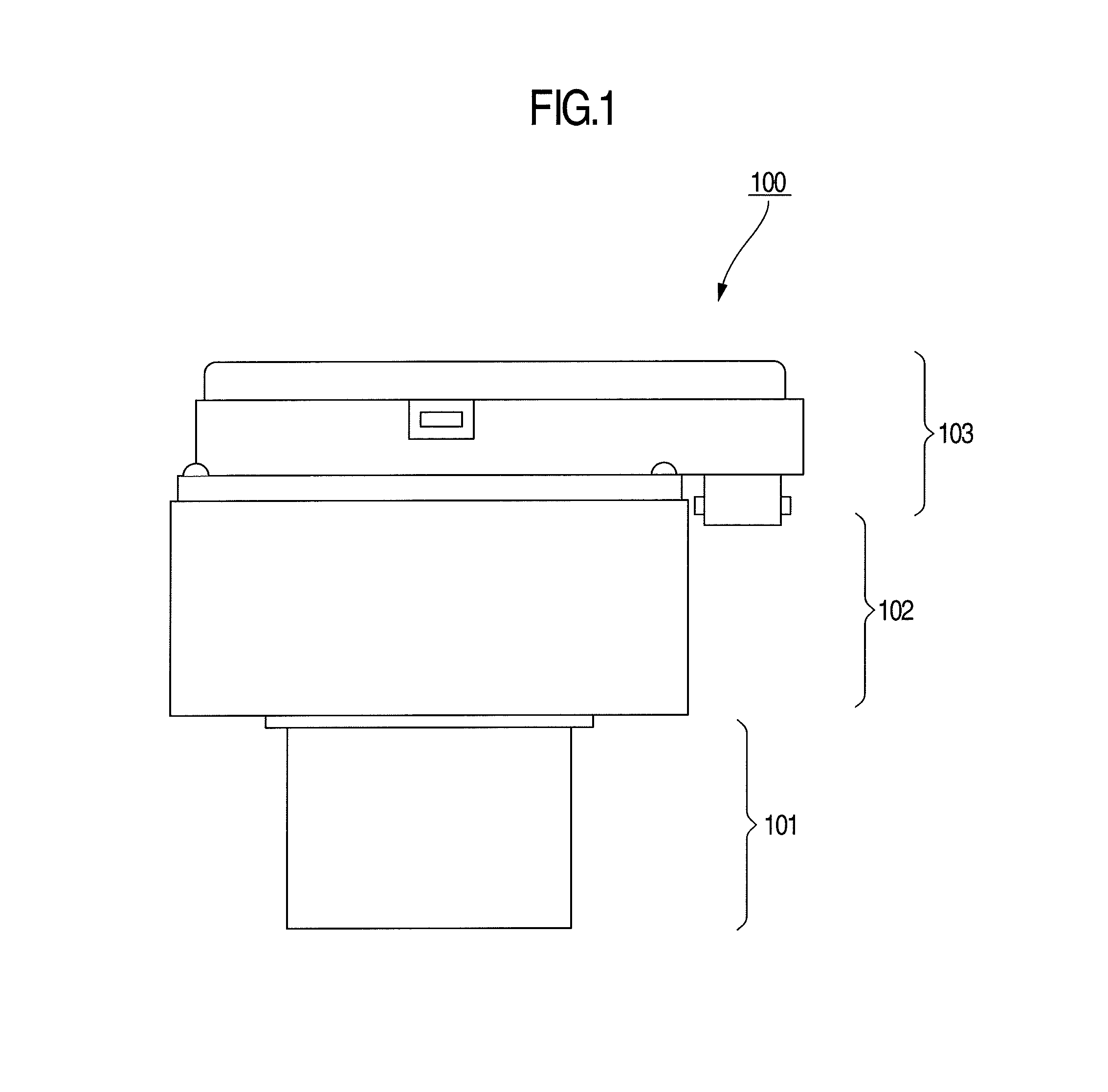
[0033]In this embodiment, description is made by exemplifying an ESC apparatus as an electric brake control apparatus. As shown in FIG. 1, the ESC apparatus 100 generally includes three units, which are a motor 101; a hydraulic unit (HU) 102 that utilizes rotational movement of the motor to generate a hydraulic pressure and determines a transmission path of the hydraulic pressure by opening and closing an electromagnetic valve; and an electronic control unit (ECU) 103 that includes a printed circuit board (PCB) for drive control of the motor and control of opening and closing the electromagnetic valve. The ESC apparatus 100 of the present invention has a configuration that connects the motor 101 to the electronic control unit via the hydraulic unit 102.

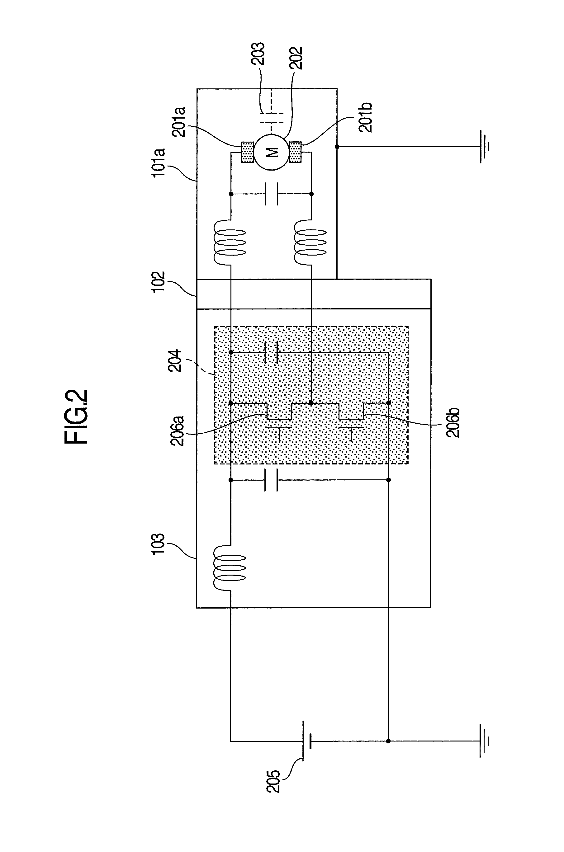
[0034]FIG. 2 is a diagram showing a conventional ESC apparatus in an equivalent circuit. A motor driving circuit in the case of adopting a DC motor as the motor of the ESC apparatus and adopting a battery 205 as a power source is repr...

embodiment 2

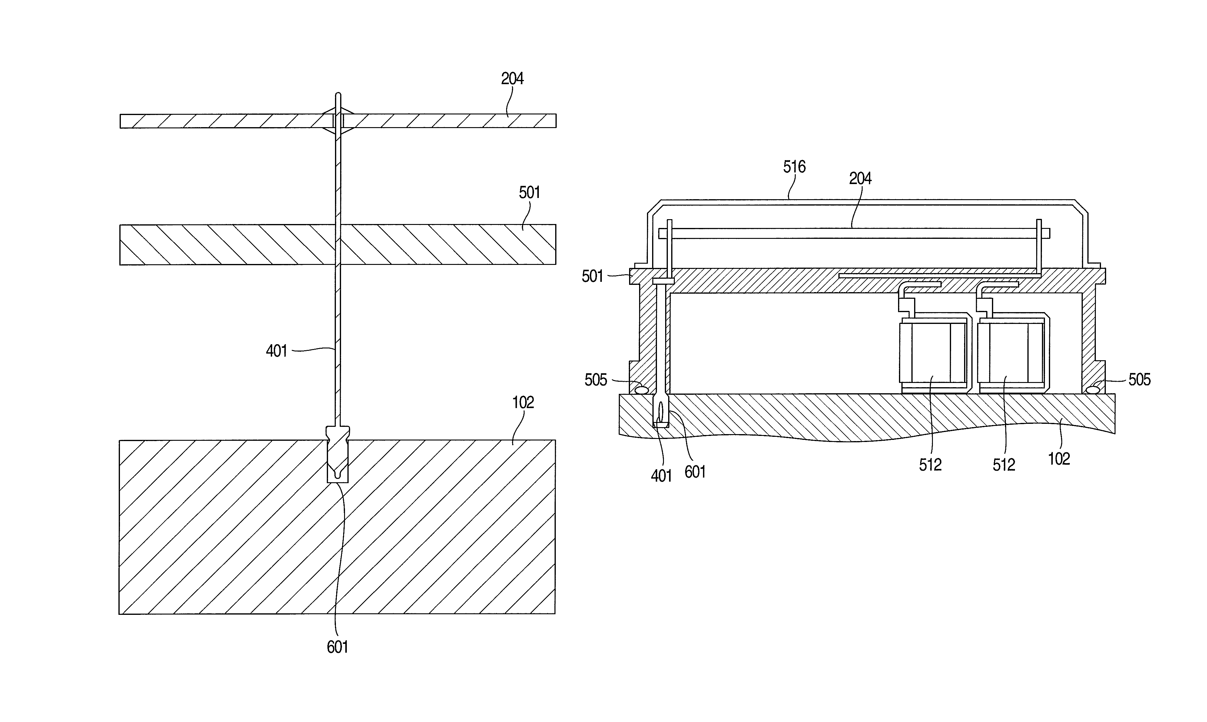
[0059]FIG. 7 is a sectional view of the structure of a part connecting, to the HU 102, of the conductor 401 that electrically connects the housing 101a of the DC motor of the ESC apparatus to the ground of the PCB 204 in Embodiment 2.

[0060]A structure is adopted where a structural member including the conductor 401 is fitted into the hole 601 formed in the HU 102. The structural member including the conductor 401 fixes this conductor 401 to the resin case 501 of the ECU. The conductor 401 is fixed at the part where the conductor 401 is connected to the PCB 204 on both of the upper and rear surfaces of the PCB 204. Portions other than the distal end on the side where the conductor 401 is connected to the HU 102 are covered with the resin of the resin case 501 of the ECU. It is sufficient that only a part required to plug the hole formed in the HU 102 is covered with resin. Accordingly, abrasion dust caused by friction between the conductor 401 and the HU 102 can be prevented from bei...

embodiment 3

[0065]FIG. 9 is a sectional view of an example of an ESC apparatus of Embodiment 3 of the present invention. A position where the conductor 401 is connected to the ground of the PCB 204 is disposed at a peripheral part of the PCB 204. A structure is adopted that allows a structural member including the conductor 401 is fitted into the hole 601 formed in the HU 102. A portion forming a part of the resin case 501 of the ECU and the conductor 401 function as a plug for the hole.

[0066]In this embodiment, a shape equivalent to the shape shown in FIG. 8 is adopted. A deformable portion is formed at the distal end of the conductor 401; the portion is deformed when the conductor 401 is inserted into the HU 102.

[0067]In order to avoid providing a position where the conductor 401 is newly inserted on a side of the resin case 501 of the ECU facing the HU 102, the conductor 401 can be inserted into a structural member having already been provided; for instance, a pin for spatial alignment betwe...


PUM


Abstract

It is an object to reduce noise leakage out of an apparatus, and improve reliability of an electric brake control apparatus. An electric brake control apparatus includes: a motor that includes a housing made of a conductive member; a control unit that performs drive control of the motor; and a hydraulic unit that includes a housing made of a conductive member, and further includes a conductive connection member that electrically connects a ground line of the control unit, the housing of the motor and the housing of the hydraulic unit to each other.

Description

INCORPORATION BY REFERENCE[0001]The present application claims priority from Japanese application JP2012-184767 filed on Aug. 24, 2012, the content of which is hereby incorporated by reference into this application.BACKGROUND OF THE INVENTION[0002]The present invention relates to a brake control apparatus using a motor as a power supply.[0003]Background arts of this technical field include JP-A-2007-290596 corresponding to U.S. Patent Publication No. 2007 / 252431. This gazette describes “in a brake fluid pressure controlling unit employed for a hydraulic brake system having an ESC function and the like for a vehicle, electronic components, such as pressure sensors, embedded in a fluid pressure controlling block are allowed to be used in a more severe noise environment without being replaced with components having high noise immunity”. In order to achieve this, the gazette also describes “a brake fluid pressure controlling unit for a vehicle, comprising: a metal fluid pressure control...

Claims


Application Information

Patent Timeline
Patent Type & Authority Patents(United States)
IPC IPC(8): F15B15/00B60T13/74B60T13/68B60T13/66B60T8/36B60T17/02H02K11/00H01R4/64H02K7/14H02K11/02
CPCF15B15/00H02K11/0089B60T8/368B60T13/662B60T13/686B60T13/745B60T17/02H02K7/14H02K11/02H01R4/64H02K11/40
Inventor YAHAGI, YASUOKOBAYASHI, MAKOTOTAKAGI, RYOTANAGASHIMA, KAZUAKI
Owner HITACHI AUTOMOTIVE SYST LTD
Why Eureka
Try Eureka