Reflection detection type measurement apparatus for skin autofluorescence

a technology of autofluorescence and detection type, applied in the field of skin autofluorescence measuring apparatus, can solve the problems of large reduction of fluorescence signal that is collected, large accuracy limitation in parts, moles,

Active Publication Date: 2015-10-13
KOREA ELECTROTECH RES INST
View PDF38 Cites 3 Cited by
  • Summary
  • Abstract
  • Description
  • Claims
  • Application Information

AI Technical Summary

Benefits of technology

[0027]The present invention also provides a reflection detection type measurement apparatus for skin fluorescence, which can increase a diagnosis possibility of diseases such as diabetes by exactly evaluating diagnosis factors such as AGEs from corrected skin fluorescence values.
[0028]The present invention also provides a reflection detection type measurement apparatus for skin fluorescence, which can improve the optical efficiency by efficiently concentrating light from a light source on the skin tissue and minimizing the specular reflection from the surface of the skin tissue, in measuring skin fluorescence.
[0029]The present invention also provides a reflection detection type measurement apparatus for skin fluorescence, which can improve the optical concentration and the optical uniformity by uniformly concentrating light irradiated from a light source to a measurement target.
[0030]The present invention also provides a reflection detection type measurement apparatus for skin fluorescence, in which an optical system and a light source system can be simply configured to conveniently perform a diagnosis process.

Problems solved by technology

However, there is a limitation in the above method that a fluorescent signal that is collected is considerably reduced as the measurement distance (d) increases to increase the measurement area of the target spot.
Particularly, such an accuracy limitation is considerably represented in parts such as moles, vessels, and wounds that are heterogeneous spots of skin.
However, the optical fiber probe has a limitation in delivery loss which occurs according to the small diameter and low numerical aperture of optical fibers.
Additionally, since both apparatuses disclosed in References 1 and 2 include optical fibers in a light-receiving unit that receives light, there is an inherent limitation in the optical fiber probe of the light-receiving unit.
Since References 1 and 2 are configured to use an optical fiber spectrometer and a linear array detector, there is a limitation in that the autofluorescence signal wavelength of AGE becomes relatively smaller in a detection area that is occupied by the linear array detector.
Also, due to the optical fiber probe and optical fiber spectrometer, it is difficult to minimize facilities.
On the other hand, the diagnosis apparatuses disclosed in References 1 and 2 have a limitation in that it is impossible to diagnose diseases such as a diabetic foot accompanied by diabetes.

Method used


Image

  • Reflection detection type measurement apparatus for skin autofluorescence
  • Reflection detection type measurement apparatus for skin autofluorescence
  • Reflection detection type measurement apparatus for skin autofluorescence

Examples


example 1

[0165]It is necessary to perform measurement on a measurement target and a reference sample, two targets that are introduced to obtain a corrected fluorescence value. Light measurement is performed on the human body's skin that is the measurement target among the two targets.

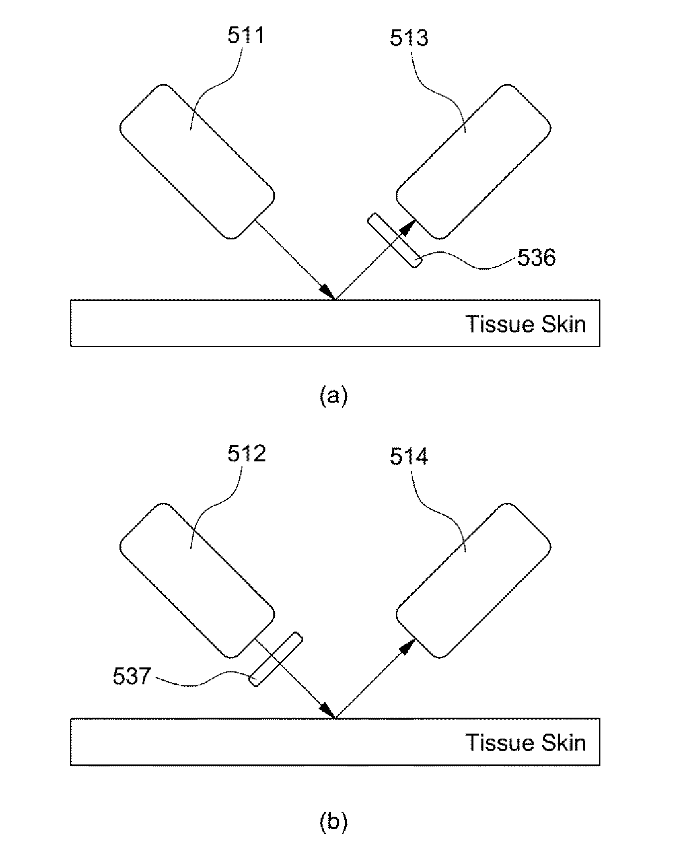
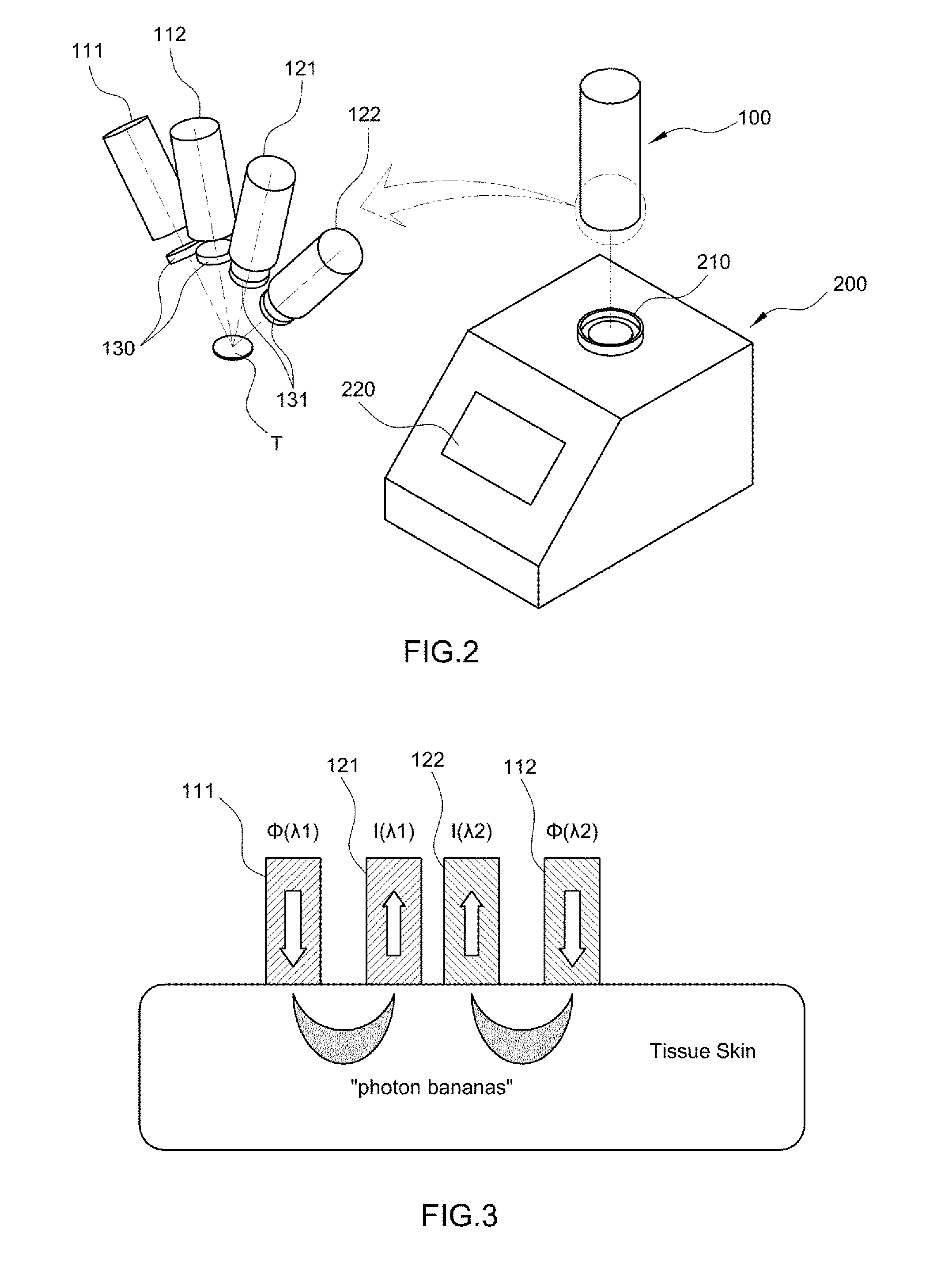
[0166]For diagnosis, the measurement is performed by a light source and an optical detector that contact or get close to the measurement target on the upper arm of a subject. A measurement scanner moves along the skin surface to scan the target part of about 5 cm2 to about 19 cm2.

[0167]Before the measurement, all light sources are turned off, and then level evaluation of a dark signal is performed to automatically compensate for light leaking from the outside.

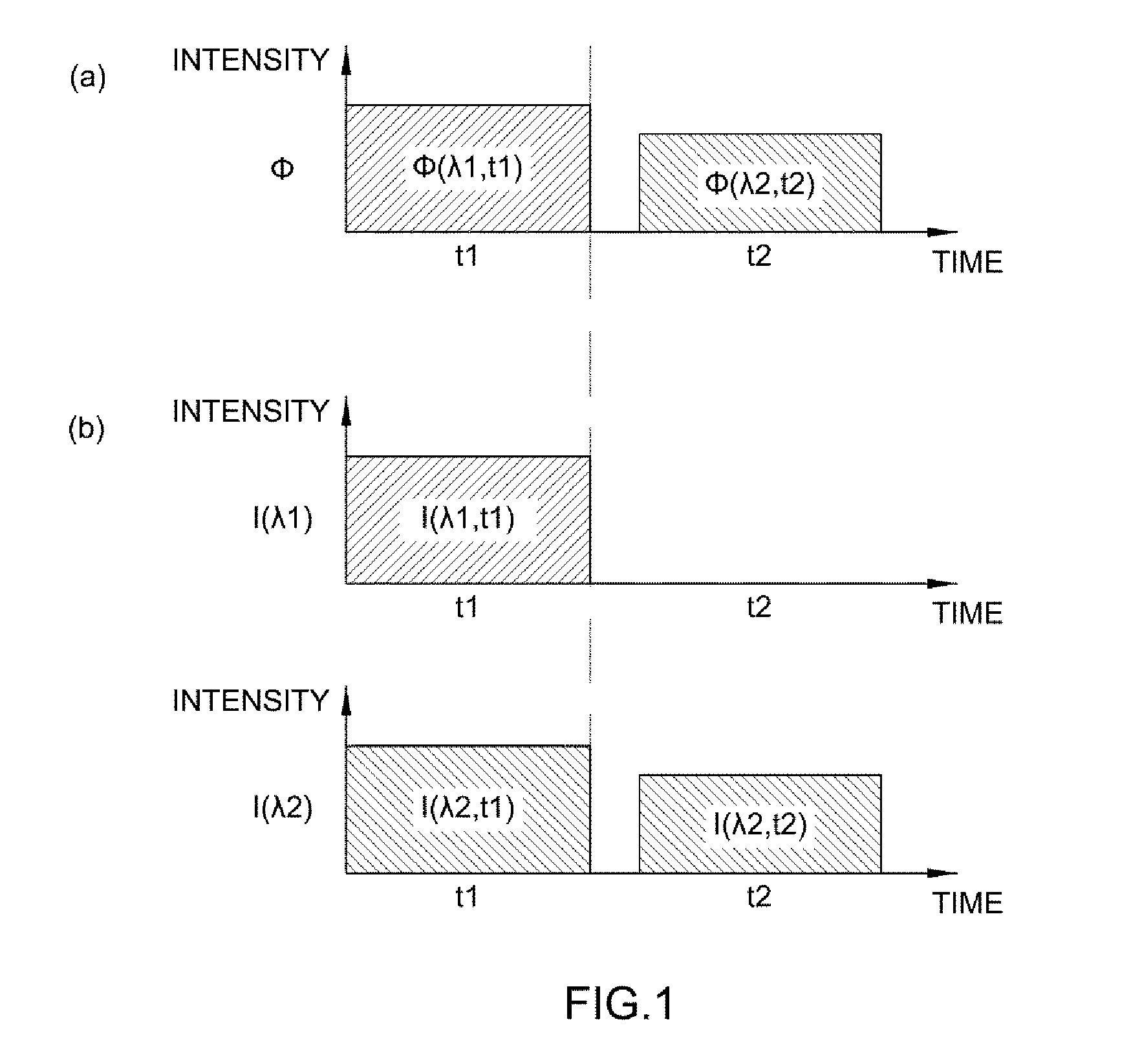
[0168]A light module sequentially generates first light source illumination light Φ(λ1, t1) with a wavelength λ1 and second light source illumination light Φ(λ2, t2) with a wavelength λ2 at different time intervals t1 and t2, respectively.

[0169]During the w...

example 2

[0195]A reflection detection type measurement apparatus for skin fluorescence including an optical prism and an optical connector was manufactured. Also, as a comparative example, an apparatus configured such that a light source and an optical detector are located similarly to those of the reflection detection type measurement apparatus and optical irradiation and optical detection are performed without the optical prism and the optical connector was manufactured.

[0196]In this test example, a UV LED (No 33, Nichia) emitting light of about 365 nm was used as the light source, and an optical fiber spectrometer (AVaspec-2048) was used as the optical detector. Also, an optical photodiode may also be used as the optical detector. A commercialized model (Right Angle Prism, Uncoated, 20 mm, Edmund Optics) was used as the optical prism.

[0197]In this test example, water was used as the optical connector, which was interposed between the optical prism and the surface of the skin that is the m...

example 3

[0259]It is necessary to perform measurement on a measurement target and a reference sample, two targets that are introduced to obtain a corrected fluorescence value. Light measurement is performed on the human body's skin that is the measurement target.

[0260]For diagnosis, the measurement is performed by a light source and an optical detector that contact or get close to the measurement target on the upper arm of a subject. A measurement scanner moves and scans along the skin surface to scan the target area of about 5 cm2 to about 19 cm2. The optical irradiation area of the reflection detection type pyramidal measurement apparatus for skin fluorescence may be about 15 mm in diameter at a time.

[0261]Before the measurement, all light sources are turned off, and then level evaluation of a dark signal is performed to automatically compensate for light leaking from the outside.

[0262]A light module sequentially generates first light source illumination light Φ(λ1, t1) with a wavelength λ...


PUM


Abstract

The present invention provides a reflection detection type measurement apparatus for skin fluorescence, which is configured to perform light irradiation and light detection on a reference sample and a measurement target.

Description

CROSS-REFERENCE TO RELATED APPLICATION[0001]This application claims under 35 U.S.C. §119(a) the benefit of Korean Patent Application No. 10-2012-0028675 filed Mar. 21, 2012, and Korean Patent Application No. 10-2012-0074250 filed Jul. 9, 2012, and Korean Patent Application No. 10-2013-0009774 filed Jan. 29, 2013, the entire contents of which are incorporated herein by reference.BACKGROUND[0002](a) Technical Field[0003]The present invention relates to a skin autofluorescence measuring apparatus for diagnosing various diseases such as diabetes, by measuring autofluorescence of the skin from Advanced Glycation End-products (AGEs) accumulated in the skin.[0004](b) Background Art[0005]Recently, various apparatuses using light for the purpose of diagnosis and treatment of diseases are being developed. Particularly, various apparatuses for diagnosing diseases using skin autofluorescence emitting out of the skin by excitation light irradiated from a light source are being developed and used...

Claims


Application Information

Patent Timeline
Patent Type & Authority Patents(United States)
IPC IPC(8): A61B6/00A61B5/00A61B5/1455A61B5/145
CPCA61B5/0071A61B5/14546A61B5/1455
Inventor KANG, UKPAPAYAN, GARRY V
Owner KOREA ELECTROTECH RES INST
Why Eureka
Try Eureka