

Bacterial identification
a technology of bacteria and identification, applied in the field of bacteria identification, can solve the problems of significant impact on the cost of food production
- Summary
- Abstract
- Description
- Claims
- Application Information
AI Technical Summary
Benefits of technology
Problems solved by technology
Method used
Image

Examples
example 1
Escherichia Coli Preparation Protocol
[0057]Growth Medium: A 1.1 g tablet of dehydrated LB medium (Sigma Aldrich) was added to 50 mL of 18 MΩ deionized water. The solution was gently heated with stirring until all solids dissolved. The solution was then covered and autoclaved.[0058]Bacterial Growth: 5 mL autoclaved LB was added to each of three sterile 10 dram vials. Strains of E. coli, frozen on small (approximately 2-mm diameter) beads, were obtained from the State of Arizona Public Health Laboratory. One bead from each strain was used to inoculate three of the four vials. The last vial of growth medium was retained as a control, to ensure that no contamination occurred. Following inoculation of the media with beads, the vials were incubated overnight at 37° C. in a shaker / incubator.[0059]Fluorescent labeling: Following incubation, optical density measurements were taken at 600 nm to ensure sufficient bacterial growth. 1-mL samples of each solution were transferred to microcentrifu...
example 2
Separation of E. Coli Serotypes
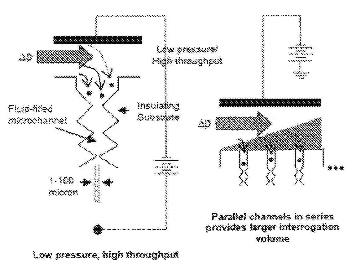
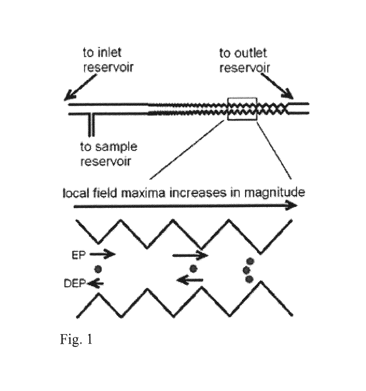
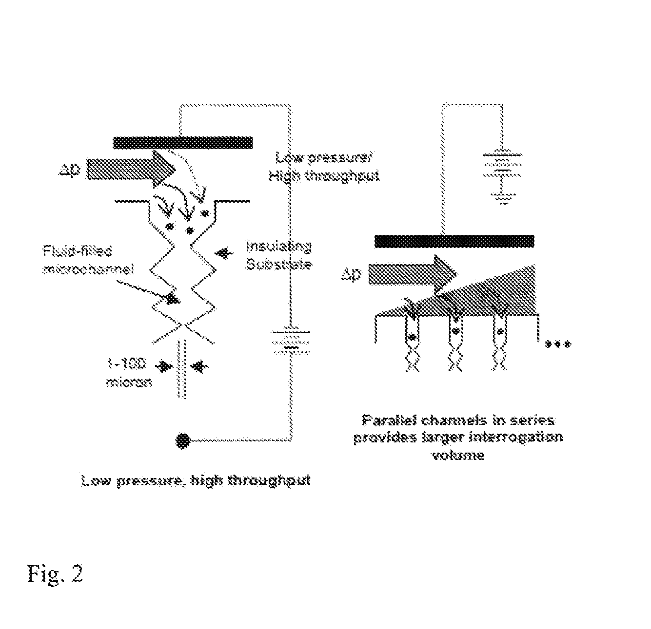
[0060]E. coli bacterial strains in buffer may be separated using DC-iGDEP apparatus. In particular, three closely related E. coli serotypes (ATCC 25922 (O6:H1); O55:H7; O157:H7) have been separated from each other using DC-iGDEP apparatus. E. coli samples were dispersed in phosphate buffer and introduced into the channel using hydrostatic pressure. The dielectromicrofluidic design is a microfluidic channel cast in dielectric insulator approximately 3 cm long by a variable width starting with 350μ at inlet, and with wall cast in an opposing sawtooth configuration with opposing sawteeth separated by varying distances ranging from 300μ to 30μ at the outlet. The channel was imaged using an Olympus IX70 inverted microscope, and the 4 cm length of the channel was scanned manually by manipulating the caliper dial of the slide stage, while the voltage on the channel was tuned. E. coli serotype ATCC 25922 (O6:H1) was trapped and concentrated at the 30μ gates be...
example 3
Images of E. Coli O157:H7 Capture in DC-iGDEP Apparatus
[0061]DC-iGDEP Apparatus using PDMS bonded to glass plates were prepared as described above. E. coli O157:H7 was introduced into the channel and electrodes were introduced. A potential of 600 volts was then applied across the chamber. FIGS. 3 through 5 show a bright field image of a portion of the chamber at 100× magnification. In each Figure, an approximate drawing of a 30 μm PDMS gate is shown as opposing isosceles triangles. Flow of the bacterial cells due to the electrical forces on the cells is from right to left in this figure. Accumulation of E. coli O157:H7 cells at a 30 μm gate in the apparatus shortly after application of the voltage is shown in FIG. 3 (solid arrow). FIG. 4 shows increasing accumulation of E. coli O157:H7 cells at the 30 μm gate (solid arrow). FIG. 5 shows the chamber shortly after the voltage has been cut off. E. coli O157:H7 cells that had been accumulating on the right side of the gate have passed t...
PUM
| Property | Measurement | Unit |
|---|---|---|
| diameter | aaaaa | aaaaa |
| depths | aaaaa | aaaaa |
| height | aaaaa | aaaaa |
Abstract
Description
Claims
Application Information