
Methods of forming a metallic or ceramic article having a novel composition of functionally graded material and articles containing the same

a functional graded material and composition technology, applied in the field of making metallic and ceramic articles, can solve the problems of increasing the cost and lead time of additional processes, limiting the use of special applications, and requiring more process steps

Active Publication Date: 2015-11-17
ETERNALOY HLDG GMBH
View PDF6 Cites 12 Cited by
  • Summary
  • Abstract
  • Description
  • Claims
  • Application Information

AI Technical Summary

Benefits of technology

[0019]The function of the second plastic powder mixture is to provide a substrate layer or zones whose primary function is to provide added fracture toughness and / or other desired properties or property combinations such as thermal and electrical conductivity, corrosion resistance, or thermal expansion coefficient, and to reduce cost. In one embodiment, the chemical composition of the second composite powder is very similar to (or at least bondable to and sinterable with) the contiguous matrix of the first plastic powder mixture. This gives a metallurgical or chemical bond that provides an interface strength that is undiminished in comparison with the two substrates.
[0030]To achieve a true engineered transition zone between the layers, steeply-grooved extrusion dies may be provided in the extrusion, injection, calendering, or dry powder delivery apparatus that provide a more intimate interface between the different green layers to provide a novel interlocking imbrication of the different materials in the transitional interface zone.
[0032]The novel joining together of green powder mixtures as functionally graded materials brings reality to the term “functional gradient.” For example, it can add properties in fewer operations to automotive components such as gears and camshafts that normally require thermal or physical operations such as heat treatment or forging that require added cost and long processing times.

Problems solved by technology

Today, the best tools exhibit the best compromises, and therefore are limited to use in special applications.
However, these additional processes add cost and lead times and often require more process steps such as brazing, forging, heat treatment, grinding, or lapping.
The external coating solution has several major disadvantages, including coating delamination and cracking in use (from different coating and substrate thermal expansion rates and from bending and surface loads) and the high CVD process temperatures required (900° C.-1200° C.) may not be consistent with the heat-treatment needed for the strength or the geometry of the sintered part.
Moreover, even with the use of high performance coatings on the surface of tools, the coatings eventually fail, and as the properties of the underlying material are insufficient to operate at cutting speeds the tool fails very quickly.
While such tools could be rejuvenated by reapplying a CVD coating, the reapplication of a coating or multiple coatings is generally not economically feasible.

Method used


Image

  • Methods of forming a metallic or ceramic article having a novel composition of functionally graded material and articles containing the same
  • Methods of forming a metallic or ceramic article having a novel composition of functionally graded material and articles containing the same
  • Methods of forming a metallic or ceramic article having a novel composition of functionally graded material and articles containing the same

Examples


example 1

FGM Solid Rods Having Different Top and Bottom Materials

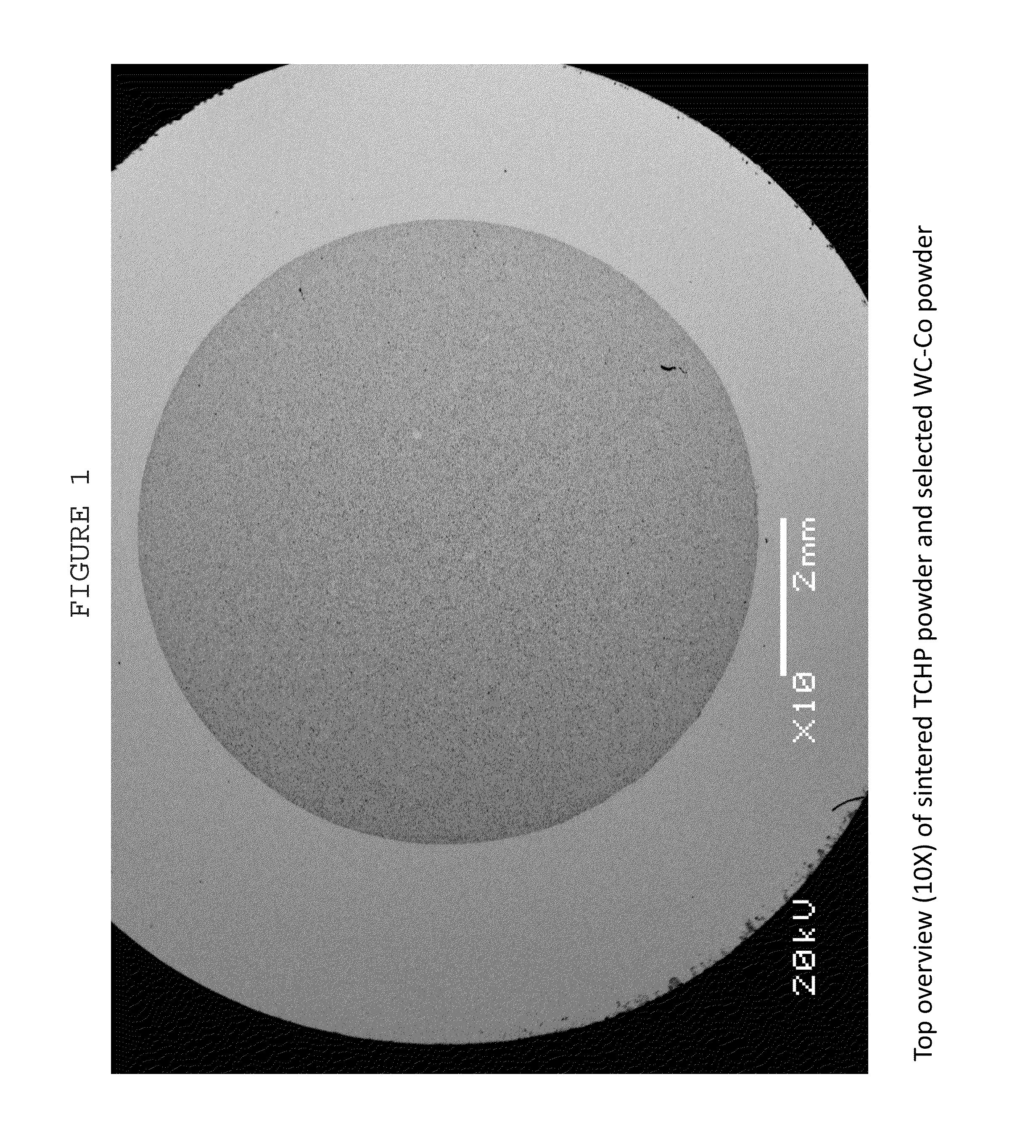
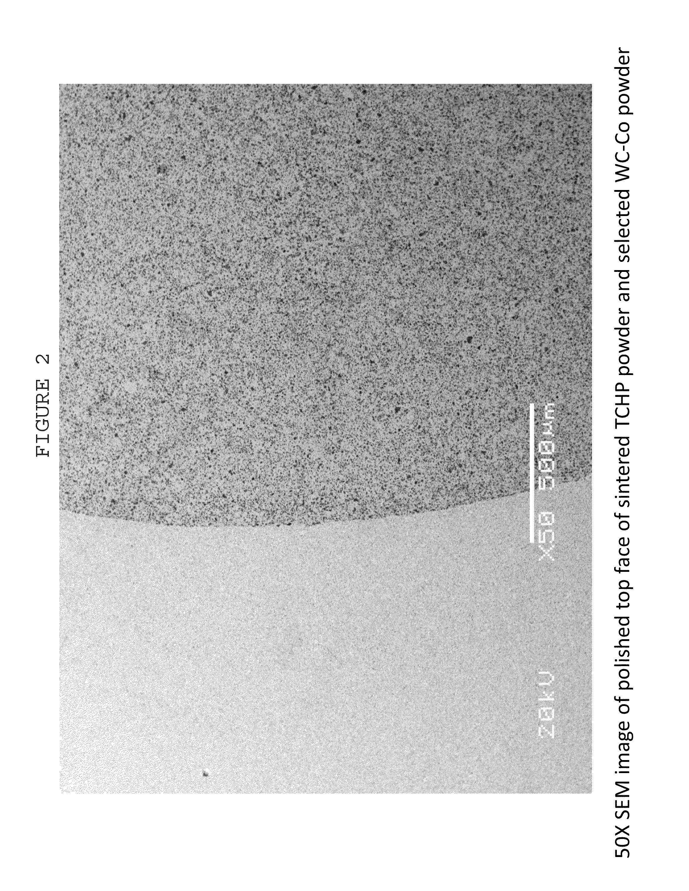
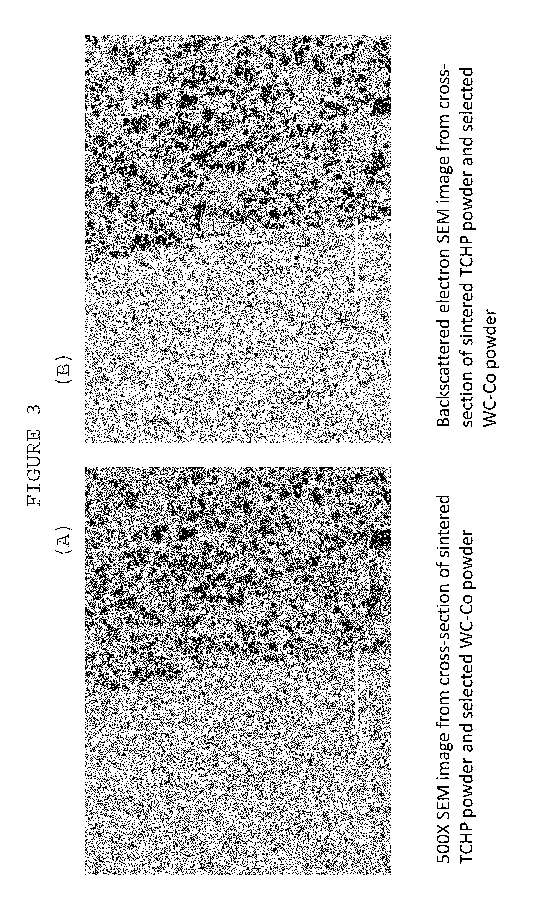
[0171]Twelve FGM two-material rods were prepared and sinter hot isostatic pressed (HIPed) according to the methods below. The rods were each comprised a top material making up ⅔ of the rod, and a bottom material making up the remaining ⅓ of the rod. Each rod made in this Example was comprised of a TCHP / WC—Co FGM Rod having a ⅜″ OD×2½″. The specific materials used for top and bottom sections were:

[0172]

Top ⅔ MaterialBottom ⅓ MaterialWC-15CoTi(C, N) core TCHP TL-3

[0173]The WC—Co material used in this example comprised 3 micron nominally sized WC with 15 wt % cobalt, and exhibited the following physical properties: Hardness (ASTM B294) of 88.0, an HRA Fracture Toughness (ISO 28079) of 11.49 MPa / m, and a Density (ASTM B311) of 14.05 g / cm3.

[0174]The TL-3 had the following Physical Properties: Hardness (ASTM B294) of 92.1, an HRA Fracture Toughness (ISO 28079) of 11.43 MPa / m, and a Density (ASTM B311) of 12.75 g / cm3.

[0175]The typical...

example 2

FGM Cylinders with Different Inner and Outer Materials

[0189]Four variations of FGM two-material cylinders were prepared and vacuum sintered as described herein, with the following inner and outer materials.

[0190]

SampleInner MaterialOuter MaterialATi(C, N) core TCHP TL-3WC-15Co GWC-50BAl2O3 core TCHP NL-3WC-15Co GWC-50CAl2O3 core TCHP NL-3Ti(C, N) core TCHP TL-3DTi(C, N) core TCHP TL-3Al2O3 core TCHP NL-3

[0191]Typical Powder Pressing Method (for FGM Cylinders)

[0192]The following provides the methodology used for powder pressing FGM Cylinders made according to the present disclosure.

[0193]A thin-walled hollow steel tube (outer diameter 0.340″) was placed into the center of the cylindrical die tooling set (diameter 0.580″) on a conventional powder press to maintain separation during loading of the two distinct powder types (“inner” and “outer” materials).

[0194]Approximately 8 grams of TCHP “inner” powder was placed in the interior of the hollow tube, and approximately 12.5 grams of “ou...


PUM

PropertyMeasurementUnit
particle sizeaaaaaaaaaa
pressureaaaaaaaaaa
temperatureaaaaaaaaaa

Abstract

There is disclosed a method of making a metallic or ceramic component, such as a cutting or forming tool, from at least two distinct powder precursors. In one embodiment, the method comprising forming a first mixture comprised of a plurality of coated particles, such as Tough-Coated Hard Powder (TCHP) composite particles created by encapsulating extremely hard core particles with very tough binder and structural materials, and at least one support powder, such as a carbide, typically WC—Co. The mixture is formed into a green body and sintered to form a functionally graded or multicomponent article. Non-limiting examples of the articles made from the disclosed methods are also disclosed and include drills, mills, cutting tools, forming tools, wires dies and mechanical components.

Description

CROSS-REFERENCE TO RELATED APPLICATIONS[0001]This application claims the benefit of U.S. Provisional Application No. 61 / 706,693 filed Sep. 27, 2012, and U.S. Provisional Application No. 61 / 736,791 filed Dec. 13, 2012, both disclosures of which are incorporated herein by reference.FIELD OF THE INVENTION[0002]The present invention relates to a method of making metallic and ceramic articles, such as drills, mills, cutting and forming tools, wire dies, and mechanical components having non-uniform compositions by forming green bodies of powders of different compositions, and compacting and sintering such green bodies.BACKGROUND OF THE INVENTION[0003]Tool life is determined by the tool's resistance to several types of wear and its response to heavy loads and to shock, with the reality that wear resistance is generally increased at the expense of strength. Today, the best tools exhibit the best compromises, and therefore are limited to use in special applications. To limit such compromises...

Claims


Application Information

Patent Timeline
Patent Type & Authority Patents(United States)
IPC IPC(8): B22F7/02B22F1/02B22F3/02B23B5/16C04B35/64C22C29/08C22C26/00B22F7/06B22F5/00B22F1/08B22F1/18
CPCB22F7/02B22F1/02B22F3/02B22F7/06B23B5/16C04B35/64C22C26/00C22C29/08B22F2005/001Y10T428/11Y10T428/12028B33Y70/00B33Y10/00B33Y80/00B22F1/08B22F1/18Y02P10/25B32B5/16
Inventor KEANE, JOHN M.TOTH, RICHARD E.
Owner ETERNALOY HLDG GMBH
Learn More