Method and system for tank refilling

a tank and tank technology, applied in the direction of container filling under pressure, liquid handling, transportation and packaging, etc., can solve the problems of reducing the final fill pressure, reducing the efficiency of hydrogen tank filling, and even more conservative parametric assumptions, so as to improve the performance of hydrogen filling stations, enhance fueling performance, and improve fill speed and fill quality.

Active Publication Date: 2015-12-15
HONDA MOTOR CO LTD
View PDF93 Cites 2 Cited by
  • Summary
  • Abstract
  • Description
  • Claims
  • Application Information

AI Technical Summary

Benefits of technology

[0006]The improved MC Method as detailed infra provides a new tank filling model based on the total heat capacity of the hydrogen fueling system and an advanced algorithm based on that model for improving the performance of hydrogen filling stations under a broad range of operating conditions and, in particular, includes additional consideration of heat transfer to the hydrogen from downstream components. This modified algorithm, as applied stepwise in the MC Method, can be used to enhance fueling performance relative to that available under SAE TIR J2601 by utilizing additional thermodynamic information about the tank and filling systems. The MC Method may be applied to virtually any combination of tank system Normal Working Pressure (NWP) and any compressed hydrogen tank system. The additional consideration of heat transfer to the hydrogen can permit fueling operations under conditions outside of current SAE TIR J2601 tables, thereby tending to improve both fill speed and fill quality (SOC %), while reducing the costs incurred by the hydrogen stations in effecting such operations.

Problems solved by technology

This tradeoff is especially significant in non-communication fueling operations in which the parametric assumptions are even more conservative.
While application of these lookup tables tends to provide for safe refilling under virtually all conditions and for virtually all tank systems, given the conservative nature of the associated assumptions, the resulting hydrogen tank filling operation may take longer, achieve lower final fill pressures and / or require lower hydrogen station pre-cooling temperatures than necessary to fill a particular tank system.
An additional limitation of the refilling procedures defined by SAE TIR J2601 is the lack of any method or procedure for a hydrogen tank filling station to compensate or adjust for situations in which its actual operating conditions fall outside of the allowed tolerances.
Efforts to avoid this out of specification condition can lead to an overdesigned hydrogen tank filling station (excessive cooling for ensuring that the pre-cooling target temperature is maintained), thereby driving up station cost.
Conversely, failing to ensure that the pre-cooling target temperature is maintained can inconvenience customers by preventing them from refilling their tanks in a timely manner (as a result of the delay(s) incurred while waiting for the pre-cooling temperature to come into specification), thereby tending to reduce customer satisfaction, station revenue and / or repeat business.
Further, operating a hydrogen fueling station with a constant pre-cooling temperature regardless of current ambient conditions increases the energy usage and reduces well-to-wheel energy efficiency.

Method used


Image

  • Method and system for tank refilling
  • Method and system for tank refilling
  • Method and system for tank refilling

Examples


Embodiment Construction

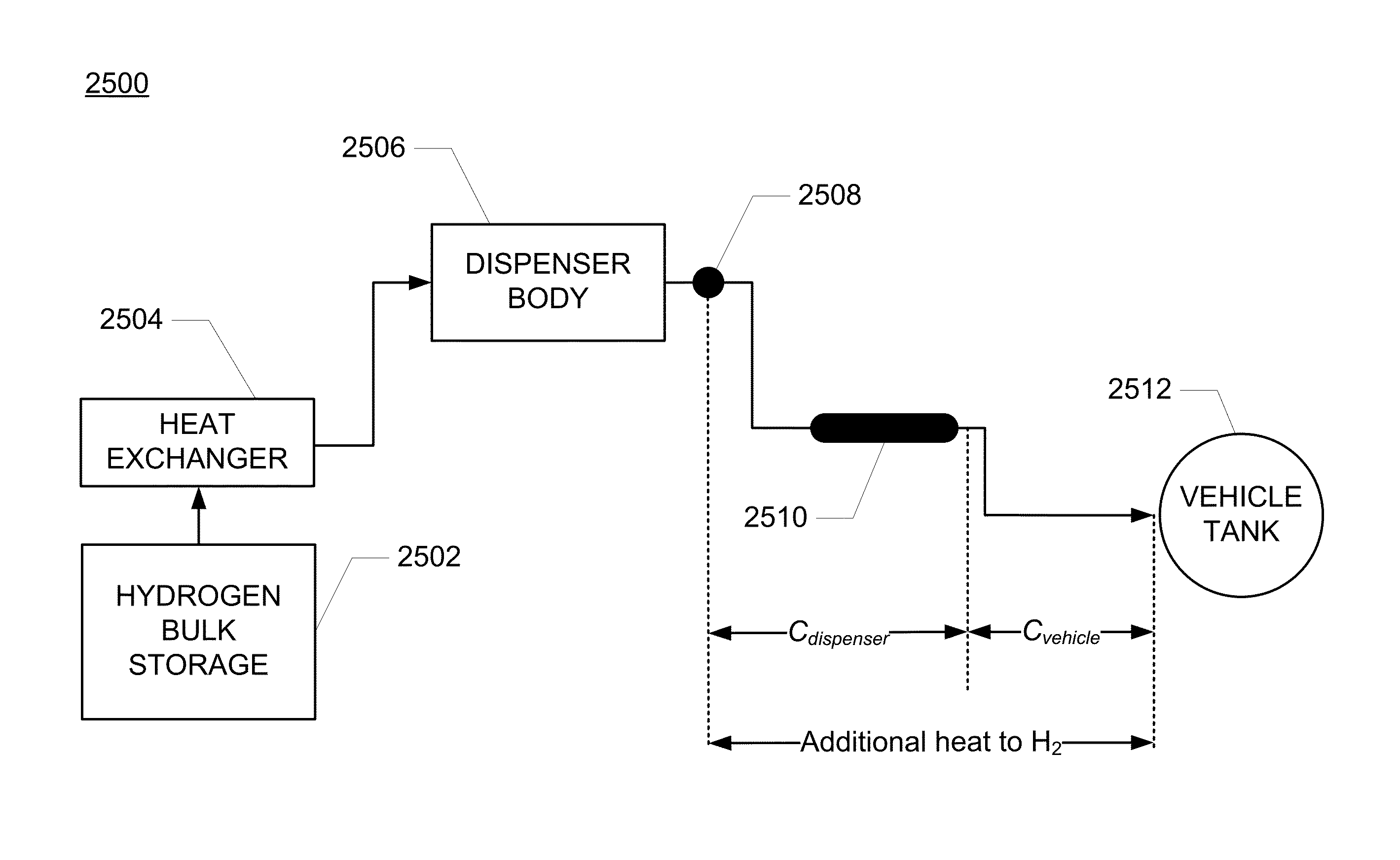
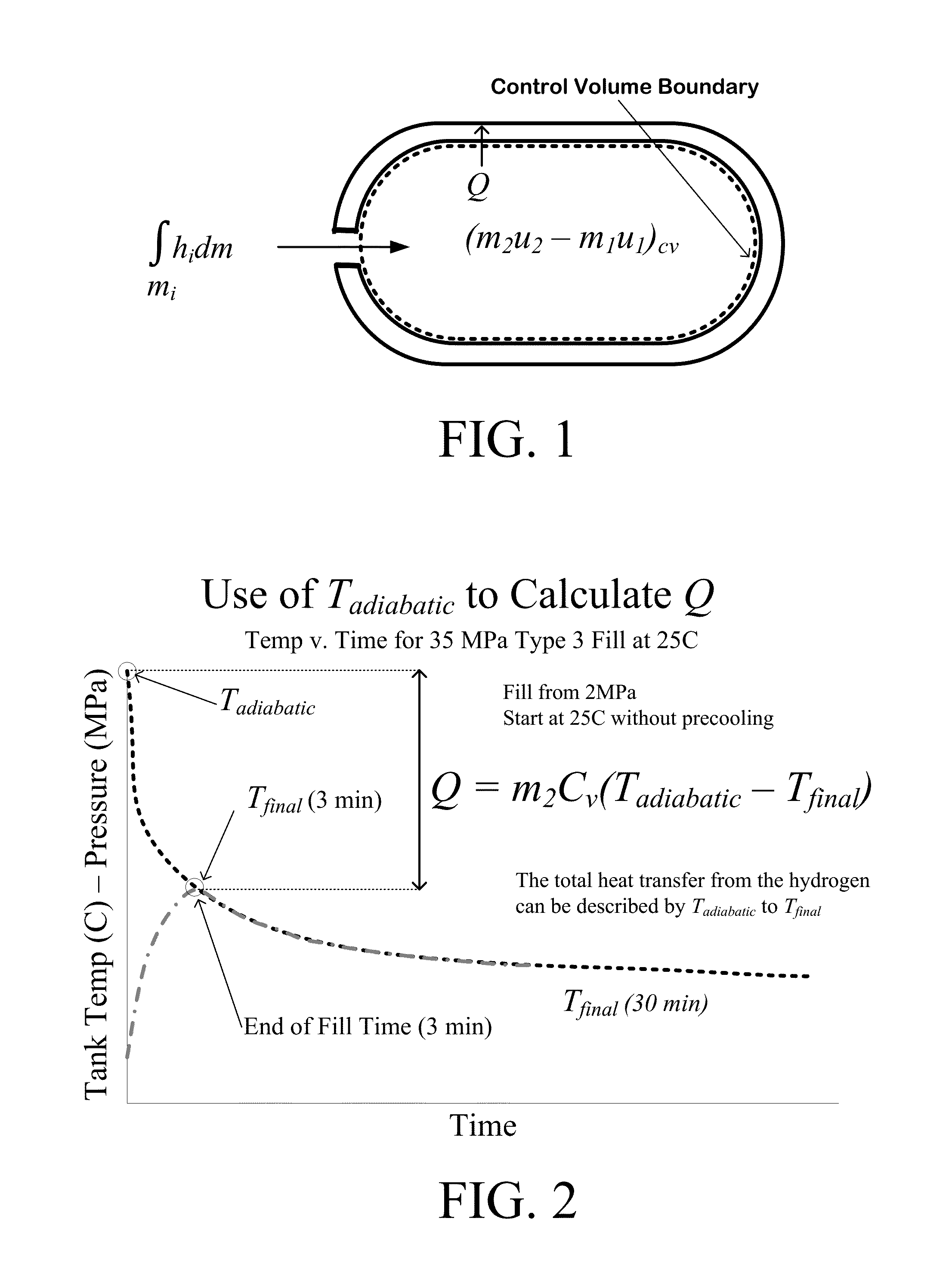
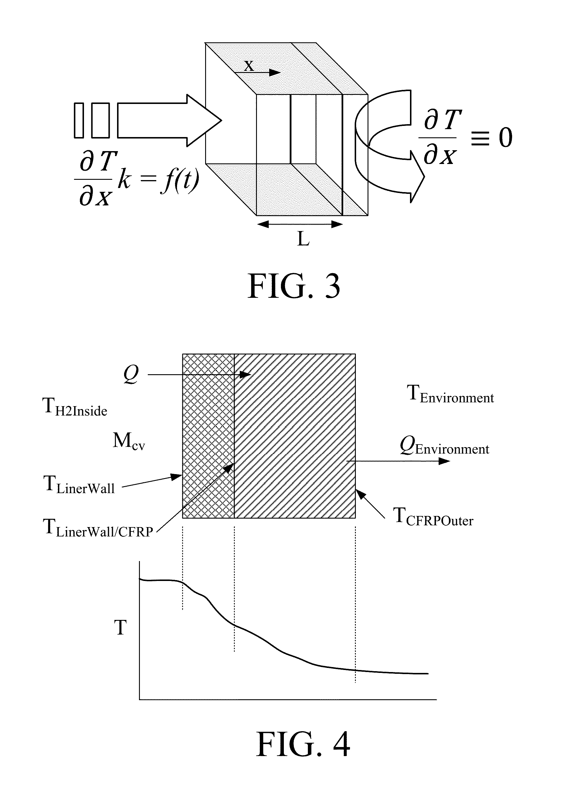
[0034]The goal of the methods and systems detailed in this disclosure is to provide an improved hydrogen filling model and system utilizing an appropriate algorithm that can be utilized in any gas tank filling operation for improving the accuracy in predicting the end-of-fill temperature and pressure conditions for a range of hydrogen tanks across a wide range of operating conditions. Implementation of the methods and systems detailed below during hydrogen tank refueling events can improve the efficiency, accuracy and / or safety of the refueling operation by reducing the chance of overfilling and / or overheating a hydrogen tank.

[0035]Accurately estimating the end-of-fill temperature achieved by a refueling operation can be difficult, which is why communication refueling has been developed. Such systems rely on temperature and pressure information that is transmitted directly to the hydrogen tank filling station through one or more communication device(s) including, for example, the In...


PUM


Abstract

Disclosed is an improved analytical method that can be utilized by hydrogen filling stations for directly and accurately calculating the end-of-fill temperature in a hydrogen tank that, in turn, allows for improvements in the fill quantity while tending to reduce refueling time. The calculations involve calculation of a composite heat capacity value, MC, from a set of thermodynamic parameters drawn from both the tank system receiving the gas and the station supplying the gas. These thermodynamic parameters are utilized in a series of simple analytical equations to define a multi-step process by which target fill times, final temperatures and final pressures can be determined. The parameters can be communicated to the station directly from the vehicle or retrieved from a database accessible by the station. Because the method is based on direct measurements of actual thermodynamic conditions and quantified thermodynamic behavior, significantly improved tank filling results can be achieved.

Description

PRIORITY STATEMENT[0001]This application is a continuation-in-part of U.S. patent application Ser. No. 12 / 982,966, filed Dec. 31, 2010, now U.S. Pat. No. 8,783,303, the contents of which are incorporated by reference, in their entirety, which claims priority pursuant to 35 U.S.C. §119(e) from U.S. Provisional Patent Application Nos. 61 / 326,375 and 61 / 332,919, the contents of which are incorporated by reference, in their entirety.BACKGROUND OF THE INVENTION[0002]The safety and convenience of hydrogen tank refueling are recognized as important considerations in determining the ultimate success of hydrogen fueled vehicles in the marketplace. Under current safety guidelines, the refueling of compressed hydrogen tanks are to be conducted in a manner that prevents the tank from overheating (temperatures exceeding 85° C.) during refueling and / or from overfilling the tank to a point at which the pressure could exceed 125% of normal working pressure (NWP) at any time. Because of the number o...

Claims


Application Information

Patent Timeline
Patent Type & Authority Patents(United States)
IPC IPC(8): F17C5/06F17C5/00
CPCF17C5/06F17C5/007F17C2201/0109F17C2201/054F17C2203/0604F17C2203/0619F17C2203/0624F17C2221/012F17C2221/033F17C2223/0123F17C2223/0153F17C2223/0161F17C2223/036F17C2225/0123F17C2225/036F17C2250/043F17C2250/0439F17C2250/0443F17C2250/0491F17C2250/0495F17C2250/0631F17C2250/0694F17C2260/022F17C2260/023F17C2260/025F17C2260/026F17C2265/065F17C2270/0139F17C2270/0168F17C2270/0176Y02E60/321Y02E60/32
Inventor MATHISON, STEVEN
Owner HONDA MOTOR CO LTD
Why Eureka
Try Eureka