Visual display system using multiple image sources and heads-up-display system using the same

a visual display system and image source technology, applied in optics, instruments, optical elements, etc., can solve the problems of low reliability, low system latency, and frequent and expensive maintenance of crt displays, and achieve low system latency, high contrast ratio, and high luminance

Active Publication Date: 2016-01-26
ROCKWELL COLLINS INC
View PDF54 Cites 47 Cited by
  • Summary
  • Abstract
  • Description
  • Claims
  • Application Information

AI Technical Summary

Benefits of technology

[0020]The present invention combines the benefits of vector scan display and raster scan display technologies for providing a solution for a visual display system which requires extremely high luminance, high contrast ratio, low system latency, and low power consumption. The present invention is compact and highly reliable. It can produce images with quality as h

Problems solved by technology

First, they have relatively low reliability because of their high operating voltage.
For applications that require high reliability under harsh environmental conditions, CRT displays require frequent and expensive maintenance.
Second, CRT displays have a limit on resolution, because of their magnetic-deflecting mechanisms.
This imposes not only a limit on the resolution of the image, but also restricts the maximum information content to be displayed.
Compared to other display products of the same size, CRT displays are relatively bulky and heavy, not to mention the volume and weight of their high voltage power supplies.
When a CRT operates in the dual mode, raster mode and stroke mode in a time sequential manner, to display high brightness symbology and relatively low brightness video images together, both raster video resolution and the symbology content are limited.
In addition, the analog nature of CRT displays has prevented them from being implemented in many digital applications.
However, liquid crystal displays, although improved dramatically over last ten years, still suffer by relatively poor optical performance.
There are two prominent performance issues associated with liquid crystal displays: 1) Low contrast due to light leakage from the light valve of the OFF pixels; and, 2) Motion artifact due to the slow electro-optical response of liquid crystal material, and the addressing scheme.
Low contrast ratio severely reduces the dynamic range of the image, and causes the dark background of the image to “glow”.
This is particularly problematic when viewing the display in dark ambient.
The background glow can be very disturbing and distracting.
The motion artifact not only degrades the overall quality of the image, but also may cause important information on the image to be blurred

Method used


Image

  • Visual display system using multiple image sources and heads-up-display system using the same
  • Visual display system using multiple image sources and heads-up-display system using the same
  • Visual display system using multiple image sources and heads-up-display system using the same

Examples


Embodiment Construction

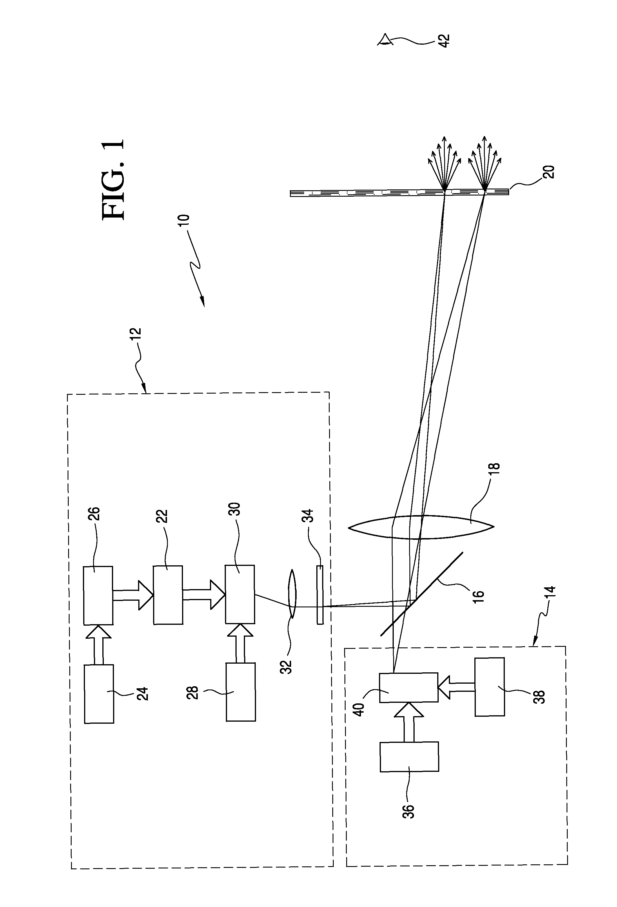
[0025]Referring now to the drawings and the characters of reference marked thereon, FIG. 1 illustrates a visual display system, designated generally as 10, in accordance with the principles of the present invention.

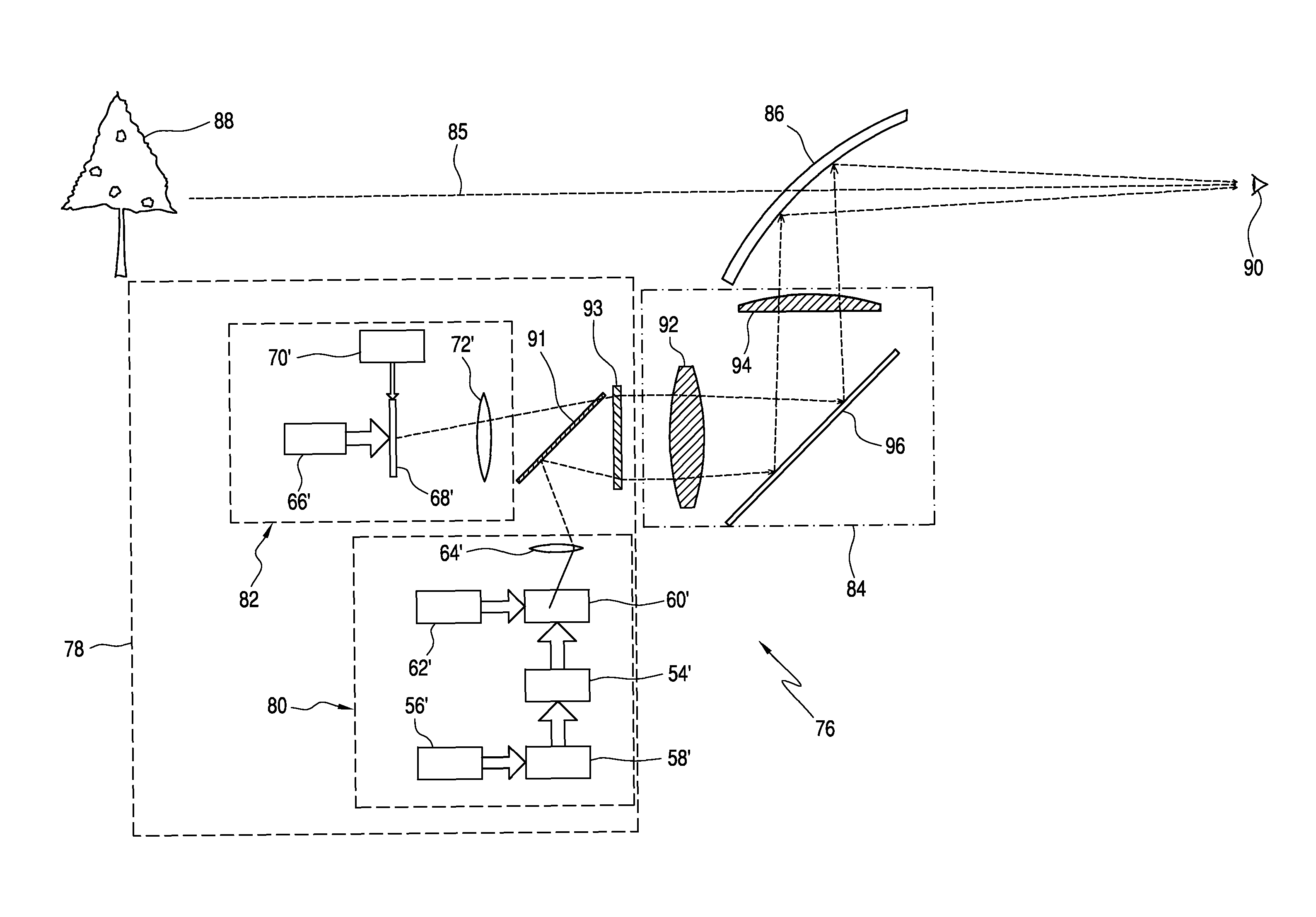
[0026]The visual display system includes a first image source, designated generally as 12, for producing a first image containing high luminance symbological information using a vector drawing system. A second image source 14 produces a second image containing video, graphical, and / or symbology information with a brightness lower than the brightness of the first image. The second image source 14 employs a raster or vector scan scheme to generate the image. A light combining optical element 16 combines the light from the first and the second image sources 12, 14. An image forming optical system 18 receives the combined light from the light combining optical element 16 for forming a new image comprising a superimposition of the first image and the second image at a final im...


PUM


Abstract

A visual display system includes a first image source for producing a first image containing symbological information using a vector drawing system. A second image source produces a second image containing video, graphical, and/or symbology information with a brightness lower than the brightness of the first image. A light combining optical element combines the light from the first and the second image sources. An image forming optical system receives the combined light from the light combining optical element for forming a new image comprising a superimposition of the first image and the second image at a final image plane of the system. A light receiving element, located at the final image plane of the system, receives the new image from the image forming optical system and adjusts the characteristics of the light from the new image to generate a final image for direct or indirect viewing. The visual display system is particularly adaptable for use in a Heads-Up-Display (HUD) system.

Description

BACKGROUND OF THE INVENTION[0001]1. Field of the Invention[0002]The present invention is related to a high quality visual display system with high performance and low power consumption. In particular, the present invention is related to a visual display system using multiple image sources, each of which independently produces an image with distinct information content. The images are subsequently or simultaneously combined together in an optical system to form a final superimposed image. More particularly, the present invention is related to see-through visual display systems with very high image brightness, such as heads-up-display systems.[0003]2. Description of the Related Art[0004]Most visual display systems include a single image source. Some visual display systems include multiple image sources but usually each image source displays the same information content. The Cathode-ray-tube (CRT) has been the primary display technology for years, and is used in many types of visual di...

Claims


Application Information

Patent Timeline
IPC IPC(8): G02B27/01G02B5/02
CPCG02B5/0252G02B27/01G02B2027/0141G02B2027/0118
Inventor LI, SHU
Owner ROCKWELL COLLINS INC
Why Eureka
Try Eureka