Dialysis device and method for operating a dialysis device

a dialysis unit and dialysis fluid technology, applied in the direction of membranes, other medical devices, separation processes, etc., can solve the problems of large quantity of dialysis fluid consuming a considerable amount of additional energy, production and consumption rendering a dialysis treatment extremely costly, etc., to achieve the effect of increasing the efficiency of the dialysis uni

Active Publication Date: 2016-02-23
B BRAUN AVITUM
View PDF10 Cites 5 Cited by
  • Summary
  • Abstract
  • Description
  • Claims
  • Application Information

AI Technical Summary

Benefits of technology

[0014]In several embodiments of dialysis units a heat pump is coupled to an inlet means serving for guiding a dialysis fluid to a dialyser membrane so as to exchange thermal energy between a heat reservoir and the dialysis fluid in the inlet means. This can result in considerable reduction of the energy consumption and considerable increase in the efficiency when temperature controlling the dialysis fluid and thus in an increase in the efficiency of the dialysis unit.
[0015]In several embodiments the heat pump is used to heat the dialysis fluid in the inlet means. By using a heat pump which, compared to other heating options such as an electric direct heating, exhibits a considerably higher efficiency, the energy required to operate a dialyser can be considerably reduced. The higher efficiency when using a heat pump is due to the fact that the thermal energy output by the heat pump to the dialysis fluid is higher than the energy required to operate the heat pump, because the heat pump transfers the thermal energy from the heat reservoir to the dialysis fluid instead of generating it on its own. Thus the heat pump is superior both to other heating systems directly converting primary energy carriers into thermal energy and to conventional electric heating systems.
[0016]In several further embodiments an ambient medium such as the ambient air is used as heat reservoir. The increase in efficiency to be gained when using a heat pump, which is derived from Carnot's procedure, is dependent on the difference in temperature between the two mediums coupled by the heat pump, hence in the present case the temperature of the heat reservoir and the temperature of the dialysis fluid. This factor also referred to as coefficient of performance (COP) becomes higher, the higher the temperature of the heat reservoir relative to the temperature of the dialysis fluid. For instance, in southern countries a heat pump in the inlet means of a dialyser can heat the dialysis fluid in an especially efficient way, when the ambient air is used as heat reservoir. At the same time, when employing such heat pump the ambient air is cooled so that, apart from the required functionality for the dialyser, it can also bring about a comfortable climate for the patient.
[0018]In these embodiments, in a first operating mode the already used dialysate which is preheated and thereby has approximately body temperature can be used to serve as heat reservoir or as heat source, respectively, for the heat pump. That is to say, the energy already used to heat the consumed dialysate can be recovered in large parts to heat the fresh dialysis fluid in the inlet means. This results in a further considerable reduction of the energy consumption during dialysis, i.e. altogether in an increase in the efficiency when operating a dialysis unit / apparatus. The efficiency of heat recovery by means of a heat pump for the afore-mentioned reasons is considerably higher than the efficiency of a conventional heat exchanger, for example.
[0020]In a second operating mode, further embodiments of dialysis units / apparatuses allow to transfer thermal energy from a fluid in the inlet means to the heat reservoir in order to cool the dialysis fluid or a rinsing fluid in the inlet means. In this operating mode the dialysate or another fluid, for example, can be used in the outlet means as a heat sink. This can considerably reduce a period of time required by a dialyser after hot disinfection for cooling to an operating temperature comparable to the body temperature, as a rinsing fluid is actively cooled in the inlet means. Thereby both the fluid quantity required for rinsing and the rinsing time is reduced, which altogether results in an increase in the efficiency during operation of a dialysis unit / apparatus.
[0023]Several embodiments further include a degassing device coupled to the inlet means which serves for removing gases or air bubbles dissolved in the dialysis fluid. In several embodiments the heat pump is arranged in the flow direction of the dialysis fluid behind the degassing device so as not to additionally heat the components of the degassing device. This entails another increase in efficiency of the dialysis unit.

Problems solved by technology

Solely the large quantity of dialysis fluid to be produced and consumed renders a dialysis treatment extremely costly.
In addition to the high consumption of resources, the energy consumed to process the dialysis fluid considerably increases the costs.
Said tempering of the large quantity of dialysis fluid consumes a considerable amount of additional energy.
As further extracorporeal dialysis procedures hemofiltration or hemodiafiltration are mentioned by way of example only which partly consume even higher amounts of resources and energy and therefore incur similar or higher costs when being applied.
Due to the high consumption of resources and the high energy consumption for a dialysis treatment, there is a considerable need to render dialysis units and procedures for operating dialysis units more efficient.

Method used


Image

  • Dialysis device and method for operating a dialysis device
  • Dialysis device and method for operating a dialysis device
  • Dialysis device and method for operating a dialysis device

Examples


Embodiment Construction

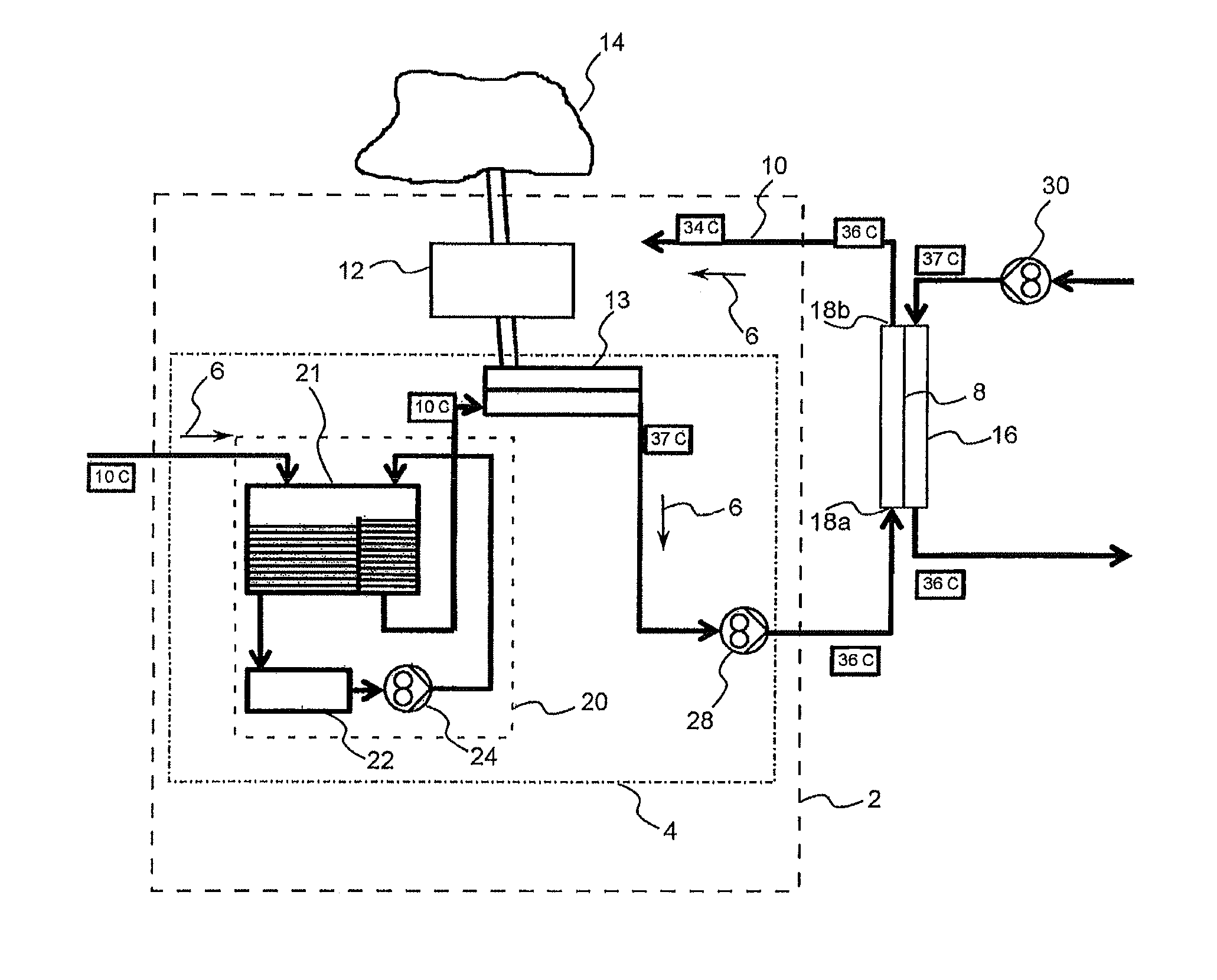
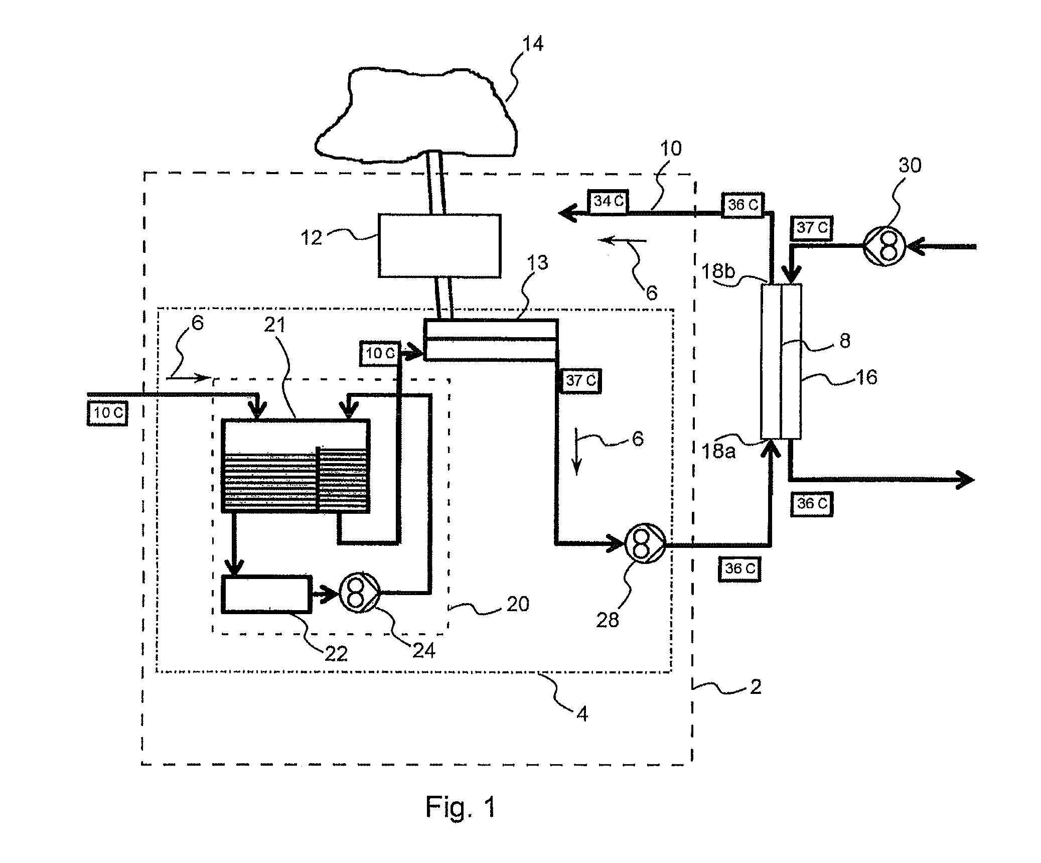
[0031]FIG. 1 illustrates an embodiment of a dialysis unit 2 having an inlet 4 so as to guide a dialysis fluid in a direction of flow 6 to a dialyser membrane 8. The dialysis unit 2 further comprises an outlet 10 for discharging a dialysate from the dialyser membrane 8. A heat pump 12 designed to exchange thermal energy between a heat reservoir 14 and the dialysis fluid in the inlet 4 is coupled to the inlet 4.

[0032]By the outlet 10 in the present case all devices or lines, are understood in which the dialysate can be guided or transported in the direction of flow 6 shown in FIG. 1 after the process of dialysis inside the dialyser 2 itself. Equally, by the inlet 4 of the dialysis unit 2 any device or line inside the dialysis unit 2 is understood which is or can be used to guide dialysis fluid or components of a dialysis fluid to the dialyser membrane 8. Consequently, by the inlet 4 especially also a tubing system or one or more devices guiding or processing the dialysis fluid are to ...


PUM

PropertyMeasurementUnit
volumeaaaaaaaaaa
temperatureaaaaaaaaaa

Abstract

A dialysis unit includes both an inlet for guiding dialysis fluid in a direction of flow to a dialyzer membrane and an outlet for discharging dialysate from the dialyzer membrane. A heat pump configured to exchange thermal energy between a heat reservoir and the dialysis fluid in the inlet is coupled to the inlet.

Description

CROSS REFERENCE TO RELATED APPLICATIONS[0001]This application is the U.S. national phase application of PCT International Application No. PCT / EP2012 / 050286 filed Jan. 10, 2012, which claims priority to European Application No. 11 157 528.8 filed Mar. 9, 2011, the contents of each application being incorporated by reference herein.FIELD OF THE INVENTION[0002]The present invention deals with a dialysis unit and a procedure of operating a dialysis unit.BACKGROUND INFORMATION[0003]Dialysis is a blood purification procedure used in the case of renal failure as a replacement method. Apart from renal transplantation, dialysis is the most important renal replacement therapy in the case of chronic renal failure and one of the possible alternative treatments in the case of acute renal failure. It is the aim of dialysis to keep the concentration of substances that are usually eliminated with the urine or are pathogenic, as the case may be, in the blood and / or in the body of the patient below a...

Claims


Application Information

Patent Timeline
Patent Type & Authority Patents(United States)
IPC IPC(8): A61M1/16B01D5/00B01D3/00
CPCA61M1/16A61M1/166A61M1/1656A61M1/1662A61M1/1664A61M1/1686A61M1/1658A61M2205/3606B01D3/007B01D5/0039B01D2313/38A61M1/1668A61M1/3623B01D2313/221
Inventor RITTER, KAI-UWE
Owner B BRAUN AVITUM
Why Eureka
Try Eureka