Laser with non-linear optical loop mirror

Active Publication Date: 2016-03-01
MENLO SYST
View PDF24 Cites 6 Cited by
  • Summary
  • Abstract
  • Description
  • Claims
  • Application Information

AI Technical Summary

Benefits of technology

The patent is about a new type of laser that can start up quickly and has a flexible repetition rate. The laser includes a non-reciprocal optical element that modifies the transmission function by adding a non-reciprocal phase offset or loss to the laser pulses. The non-reciprocal element intentionally shifts the transmission function to the left, making it non-zero and have a non-vanishing slope. This allows the laser to start up quickly and have a high repetition rate. The patent also mentions that the laser can be adjusted to have a variable length by changing the length of the cavity section or stretching the fibre section, which allows for a wide range of repetition rates.

Problems solved by technology

Method (a) is cumbersome because it relies on a comparatively slow process, which enhances frequency and amplitude noise in the laser.
A saturable absorber made e.g. from semiconductor material or carbon nano tubes is a very delicate device that is easily destroyed by applying too much optical power and which in many cases is subject to degradation, limiting the life time of such a system.
Method (b) on the other hand is cumbersome because it uses non polarisation maintaining (non PM) fibres.
This makes it difficult to operate such a laser independent of environmental changes over extended periods of time.
In the past, method (c) was cumbersome, because the laser was not self-starting or only with massive effort of using additional active modulators.

Method used


Image

  • Laser with non-linear optical loop mirror
  • Laser with non-linear optical loop mirror
  • Laser with non-linear optical loop mirror

Examples


second embodiment

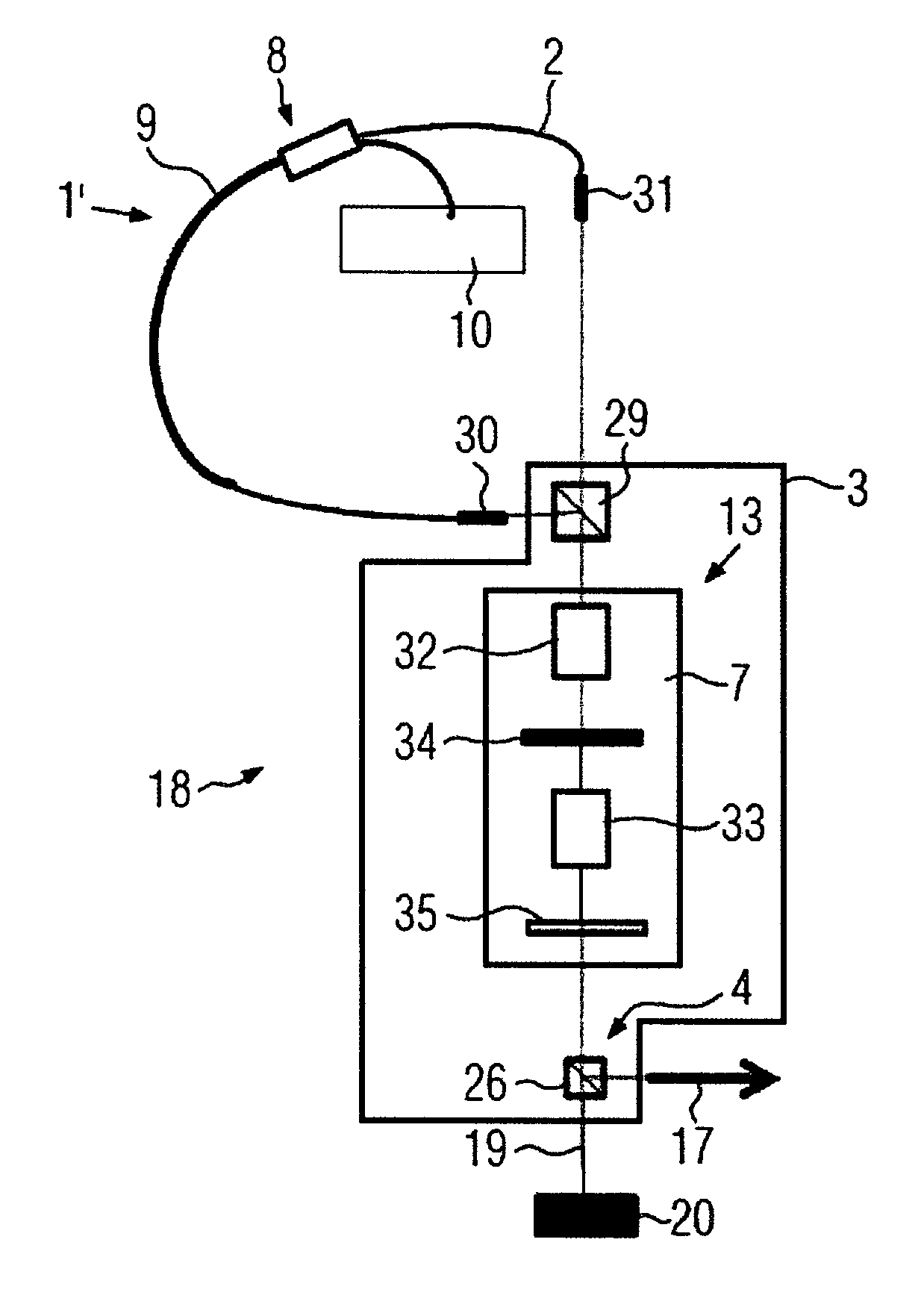
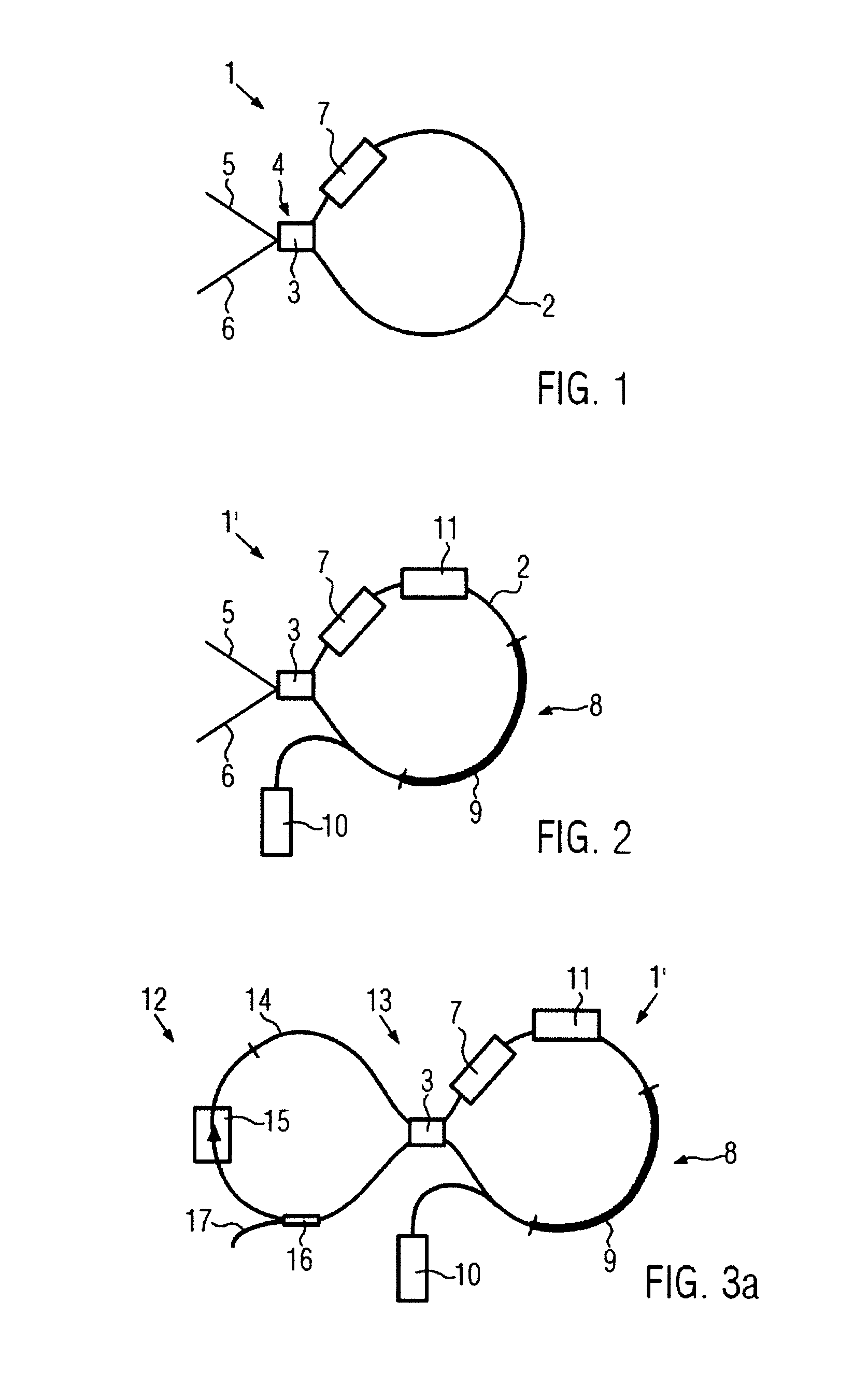
[0065]FIG. 2 shows a non-linear optical loop mirror 1′, NOLM, according to the present invention. In the embodiment of FIG. 2, the NOLM 1 is configured as a non-linear amplifying loop mirror 1′, NALM. The basic configuration of the NALM 1′ is the same as the configuration of the NOLM shown in FIG. 1. In addition, however, the NALM 1′ comprises an optical amplifier 8. The amplifier 8 comprises an active fibre section 9 inserted into the NOLM fibre 2. In FIG. 2, the active fibre section 9 is represented by a thicker curve than the remainder of the NALM 1′. In addition, the optical amplifier 8 comprises a pump source 10, in particular an optical pump source 10, in order to optically pump the active fibre section 9. Depending on the desired wavelength characteristics and the primary gain medium of the laser, the active fibre section 9 may be constituted by an Erbium, Ytterbium or Thulium doped fibre. The active fibre section 9 may also constitute the gain medium of the laser.

[0066]As an...

first embodiment

[0067]FIG. 3a shows a laser 12 according to the present invention. The laser 12 is configured as a passively modelocked pulsed laser. It comprises a laser resonator 13 which, in the present embodiment, is configured in a figure-eight geometry. In more detail, the laser resonator 13 comprises a first optical loop mirror 1, 1′. In the embodiment shown in FIG. 3a, the first optical loop mirror is configured as the NALM 1′ shown previously in FIG. 2, but could alternatively be configured as the NOLM 1 shown in FIG. 1. In particular, the first optical loop mirror 1, 1′ comprises the non-reciprocal optical element 7.

[0068]In addition, the laser resonator 13 comprises a second optical loop 14, which connects the input 5 and output 6 ports of the loop mirrors 1, 1′ and 14 to each other through a beam splitter 3. In particular, the second optical loop mirror 14 closes an optical path between the first and second ports 5, 6 of the beam splitter 3, c.f. FIGS. 1 and 2. The gain element of the l...


PUM


Abstract

In a laser (12, 18) with a laser resonator (13), the laser resonator (13) has a non-linear optical loop mirror (1, 1′), NOLM, which is adapted to guide counter-propagating portions of laser pulses, and to bring the counter-propagating portions of laser pulses into interference with each other at an exit point (4) of the NOLM (1, 1′). The non-linear optical loop mirror (1, 1′) contains a non-reciprocal optical element (7, 7′) on a linear section of the NOLM. In addition to the NOLM, the laser resonator (13) has a linear cavity section. The linear section of the NOLM and the linear cavity section (19) are reassembled on a microoptical bench (112) or within a cylindrical carrier (112).

Description

FIELD OF THE INVENTION[0001]The invention relates to a laser with a laser resonator, the laser resonator comprising a non-linear optical loop mirror, NOLM. The NOLM is adapted to guide counter-propagating portions of laser pulses, and to bring the counter-propagating portions of laser pulses into interference with each other at an exit point of the NOLM. In the context of the present invention, the term NOLM is construed to comprise NALMs, i.e. non-linear amplifying loop mirrors.DESCRIPTION OF THE RELATED ART[0002]Generally, for generation of ultra short pulses it is required to have a fixed phase relation between the modes of the laser that contribute to the output. This phase relation is fixed by mode locking the laser. There are different methods to mode lock a laser. They all rely on the fact that an element is built into the laser that favors the transmission of pulses, i.e. has higher losses for cw operation than in pulsed operation.[0003]The most commonly used methods for pas...

Claims


Application Information

Patent Timeline
IPC IPC(8): H01S3/08H01S3/11H01S3/00H01S3/067
CPCH01S3/08059H01S3/0092H01S3/06791H01S3/1112H01S3/0057H01S3/0064H01S3/06704
Inventor HAENSEL, WOLFGANGHOLZWARTH, RONALDDOUBEK, RALFMEI, MICHAELENGELBRECHT, MARTIN
Owner MENLO SYST
Why Eureka
Try Eureka