X-ray analysis apparatus with single crystal X-ray aperture and method for manufacturing a single crystal X-ray aperture

a technology of x-ray analysis apparatus and single crystal, which is applied in the direction of radiation diagnostic diaphragms, instruments, applications, etc., can solve the problems of reducing the resolution or even impairment of the correct counting behavior of the detector, the deterioration of the signal-to-noise ratio, and the accompanying significantly longer measurement times, so as to prevent the soiling of the edge, reduce the time required for step, and prevent the effect of unnecessary increase in parasitic scattering

Active Publication Date: 2016-03-08
INCOATEC
View PDF11 Cites 3 Cited by
  • Summary
  • Abstract
  • Description
  • Claims
  • Application Information

AI Technical Summary

Benefits of technology

[0023]In accordance with the invention, the X-ray aperture is formed by a one-piece single crystal which has an pinhole through which X-ray radiation can penetrate. The pinhole has an edge through which the X-ray radiation is shadowed. The pinhole widens from the edge in the beam propagation direction, whereby a sharp (preferably atomically sharp) edge can be formed and total reflections on the X-ray aperture beyond the edge can also be prevented.
[0070]In one preferred variant of the post-processing method, the aperture body is single crystal and has a through pinhole such that the edge on the single crystal aperture body is formed as a circumferential continuous edge that delimits the X-ray beam, starting from which edge the pinhole widens like a funnel in a first area towards an outlet opening, and material is also removed from the surface of the aperture body in the first area through ion beam etching, wherein the pinhole preferably has a round, in particular, circular cross-section at least in the area of the edge and of the first area. The edge quality of a single crystal aperture body can be improved to a particularly great extent through ion beam etching. The round pinhole geometry enables use of a round primary beam stop and improves the resolution compared with square beam cross-sections.

Problems solved by technology

The X-ray radiation that is incident on the apertures can be parasitically scattered which leads to an undesired increase in background radiation and therefore to a deterioration of the signal-to-noise ratio.
With small angles, parasitic scattering at the apertures is particularly strong and results in increased measurable intensities around the primary beam stop which are superimposed on the measurement signals of the sample, which can cause reduction of the resolution or even impairment of the correct counting behavior of the detector.
The disadvantage of this design with 3 pinhole apertures consists in the massive reduction of the photon flux and accompanying considerably longer measuring times and also in the large space requirement of these measuring devices.
When the X-ray beam is larger than the sample, the background noise increases e.g. due to scattered radiation of the sample holder and thereby deteriorates the signal-to-noise ratio.
The parasitic scattering at the pinhole apertures further deteriorates the signal-to-noise ratio.
If the resolution around the primary beam is decisive, e.g. in protein crystallography, only very small pinhole apertures can be integrated when the primary beam stop size remains the same, which, in turn, greatly reduces the photon flux and correspondingly prolongs the measuring time.
One disadvantageous property of these pinholes is the relatively strong parasitic scattering of X-ray radiation.
However, they are difficult to produce.
The X-ray apertures are also difficult to adjust, in particular, with respect to relative positioning of the blades.

Method used


Image

  • X-ray analysis apparatus with single crystal X-ray aperture and method for manufacturing a single crystal X-ray aperture
  • X-ray analysis apparatus with single crystal X-ray aperture and method for manufacturing a single crystal X-ray aperture
  • X-ray analysis apparatus with single crystal X-ray aperture and method for manufacturing a single crystal X-ray aperture

Examples


first embodiment

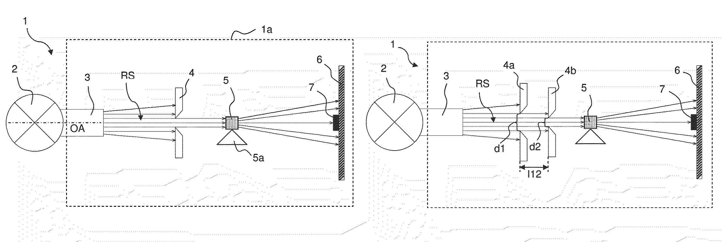
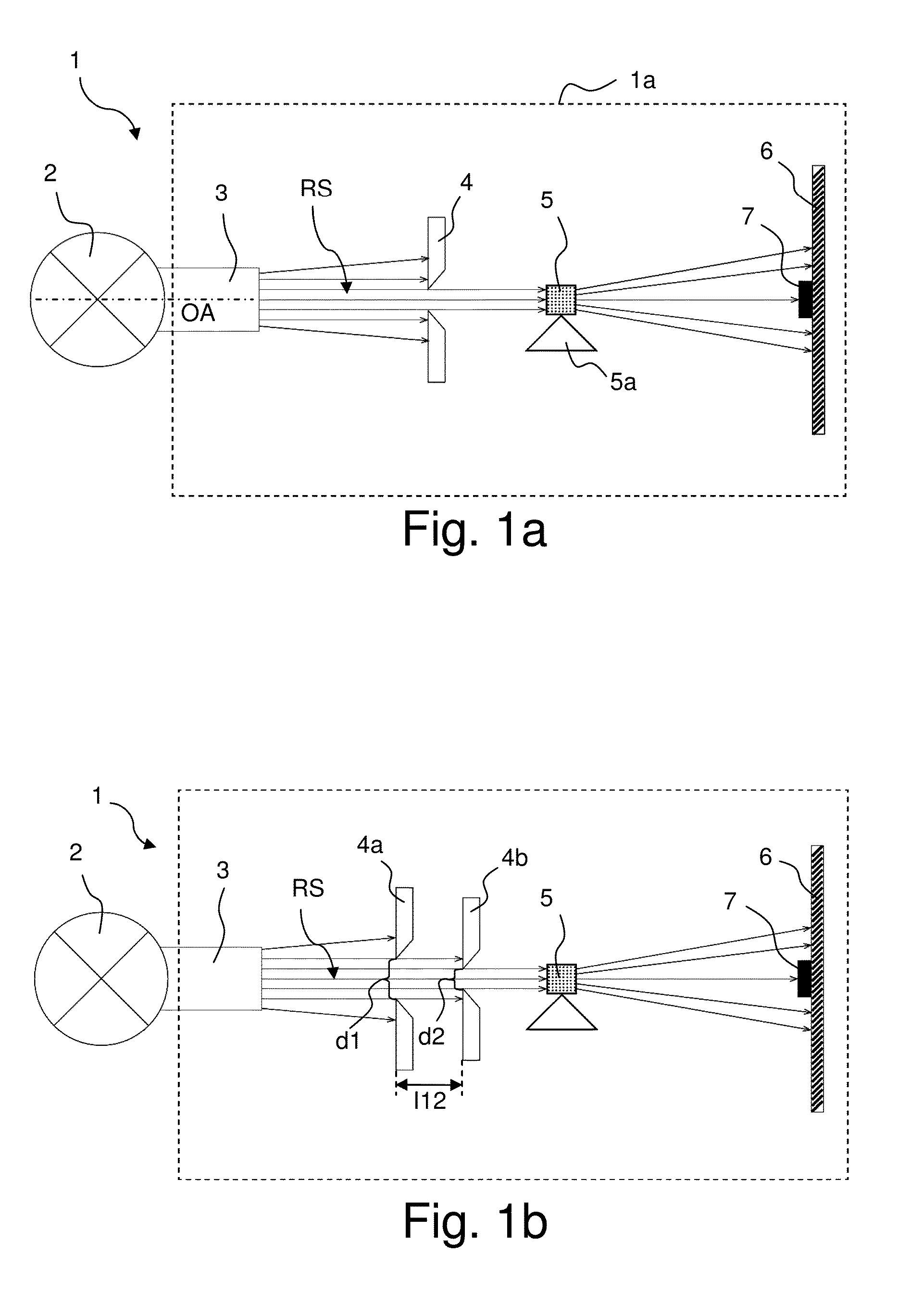
[0118]FIG. 1a shows a schematic view of an inventive X-ray analysis apparatus 1. The X-ray analysis apparatus 1 can e.g. be used for a SAXS or SCD measurement.

[0119]The X-ray analysis apparatus 1 comprises an X-ray source 2, e.g. an X-ray tube, in the simplest case with a fixed anode. An X-ray beam RS emitted by the X-ray source 1 is reshaped by a beam-shaping element 3 (in the present case approximately parallelized by a Goebel or Montel mirror) and directed to an X-ray aperture 4. In the illustrated embodiment, the beam-shaping element 3 is directly mounted to the X-ray source 2 and the X-ray aperture 4 is disposed at a distance from the beam-shaping element 3.

[0120]The X-ray aperture 4 has a single crystal aperture body (in this connection see below, e.g. FIG. 2) and widens like a funnel in the propagation direction of the X-ray beam RS (in FIG. 1 from the left-hand side to the right-hand side, cf. optical axis OA). The X-ray aperture 4 blocks an outer part of the X-ray beam RS, ...

second embodiment

[0123]FIG. 1b shows an inventive X-ray analysis apparatus 1 which largely corresponds to the embodiment of FIG. 1a. For this reason, only the substantial differences are described below.

[0124]The X-ray analysis apparatus 1 has two X-ray apertures 4a, 4b with single crystal aperture body (see below), each of which widens like a funnel in the beam propagation direction. The X-ray apertures 4a, 4b each block an outer part of the X-ray beam RS, wherein no or only very little parasitic scattered radiation is generated.

[0125]The X-ray apertures 4a, 4b are arranged between the X-ray source 2 and the sample 5. Both X-ray apertures 4a, 4b are arranged at a separation from the sample 5. In SAXS measuring arrangements, the aperture diameters d1, d2 and the aperture separation l12 are selected in correspondence with the required divergence and the beam cross-section of the respective measuring arrangement (it should be noted that the aperture diameters d1, d2 of the X-ray apertures 4a, 4b can b...

third embodiment

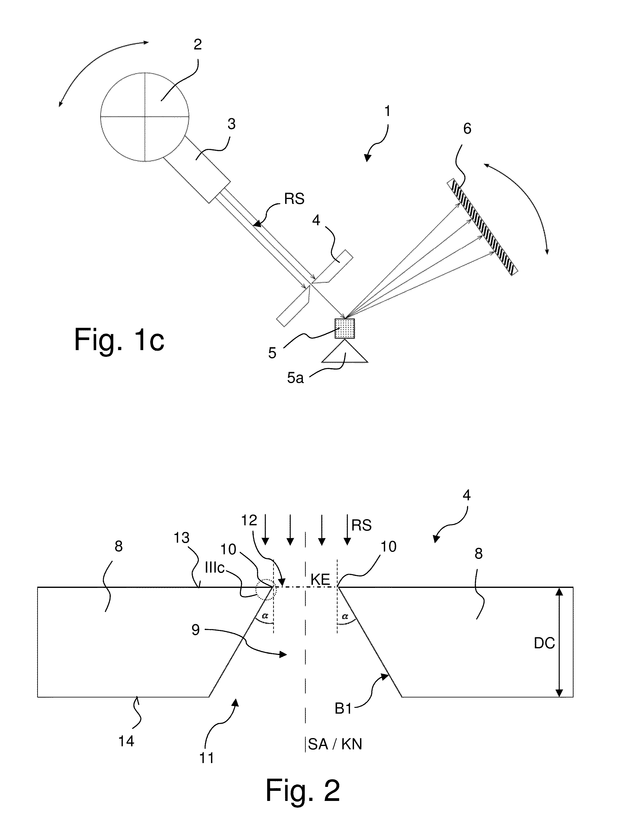
[0126]FIG. 1c schematically shows a top view of an inventive X-ray analysis apparatus 1, which is particularly suited as a μ-XRD measuring arrangement. Also in this case, only the essential differences with respect to the embodiment of FIG. 1a are explained.

[0127]In this case, the X-ray source 2 can be rotated, together with the beam-shaping element 3 and the X-ray aperture 4 with single crystal aperture body, relative to the sample 5 on the sample holder 5a, wherein the associated axis of rotation extends perpendicularly to the plane of the drawing of FIG. 1c. The detector 6 can also be rotated about the same axis of rotation (goniometer structure). Since the X-ray aperture 4 with single crystal aperture body is used, it is possible to work with large aperture diameters or high photon fluxes, at the same time strictly delimiting the X-ray beam RS to the sample 5 or to a small area or a small volume of the sample 5.

[0128]FIG. 2 shows a cross-sectional view of an X-ray aperture 4 (wh...


PUM

PropertyMeasurementUnit
wavelengthaaaaaaaaaa

Abstract

An X-ray analysis apparatus has at least one X-ray aperture (4; 4a, 4b) which delimits an X-ray beam (RS) emitted by an X-ray source (2). The at least one X-ray aperture (4; 4a, 4b) is disposed at a separation from the sample (5) and has a single crystal aperture body (8) with a through pinhole (9). The single crystal aperture body (8) forms a peripheral continuous edge (10) which delimits the X-ray beam (RS) and starting from which the pinhole (9) widens like a funnel in a direction of an outlet opening (11) of the X-ray aperture (4; 4a, 4b) in a first area (B1). The X-ray analysis apparatus reduces impairment of X-ray measurements due to parasitic scattered radiation and at little expense.

Description

[0001]This application claims Paris convention priority of DE 10 2012 208 710.9 filed May 24, 2012 the entire disclosure of which is hereby incorporated by reference.BACKGROUND OF THE INVENTION[0002]The invention concerns an X-ray analysis apparatus comprising[0003]an X-ray source from which an X-ray beam is emitted,[0004]at least one X-ray aperture which delimits the X-ray beam emitted by the X-ray source,[0005]a sample onto which the X-ray beam, which is delimited by the at least one X-ray aperture, is directed, and[0006]an X-ray detector for detecting X-ray radiation emanating from the sample,wherein the at least one X-ray aperture is disposed at a separation from the sample.[0007]An X-ray analysis apparatus of this type is disclosed by Youli Li et al., J. Appl. Cryst. (2008) 41, 1134-1139.[0008]X-ray measurements, in particular, X-ray diffractometry and small angle X-ray scattering are used for qualitative and quantitative chemical analysis as well as for the structural analysis...

Claims


Application Information

Patent Timeline
Patent Type & Authority Patents(United States)
IPC IPC(8): G21K1/02G02B26/00G21K1/04A61B6/06G01N23/20G02B26/08G01N23/201G01N23/207G02B27/09
CPCG01N23/20008G02B26/001G21K1/02G21K1/04A61B6/06G01N23/201G01N23/207G02B26/0808G02B27/0988G21K1/046
Inventor KLEINE, ANDREASKREITH, JOSEFHERTLEIN, FRANK
Owner INCOATEC
Why Eureka
Try Eureka