Eureka AIR delivers breakthrough ideas for toughest innovation challenges, trusted by R&D personnel around the world.

Process for high severity catalytic cracking of crude oil

a crude oil and crude oil technology, applied in the field of fluidized catalytic cracking process, can solve the problem that the low carbon content of catalyst particles from the low boiling fraction downflow reactor is insufficient to provide the necessary heat, and achieve the effect of maximizing production

Active Publication Date: 2016-03-22
SAUDI ARABIAN OIL CO
View PDF15 Cites 19 Cited by
  • Summary
  • Abstract
  • Description
  • Claims
  • Application Information

AI Technical Summary

Benefits of technology

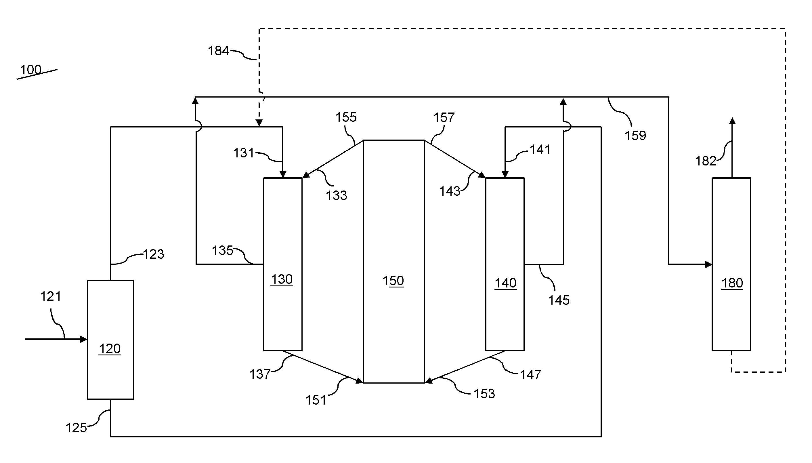
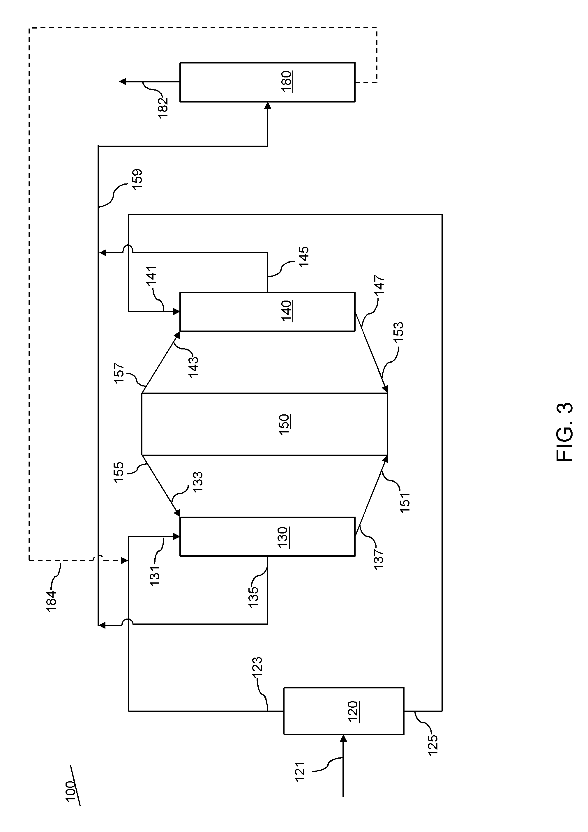
[0014]The system and process herein provides a fluid catalytic cracking process concerned with maximizing the production of light olefins, and particularly of propylene, using readily available raw crude oil as a starting feedstock within a two down-flow reaction zones operated at high severity conditions. In the FCC process and system, the feedstock is whole crude oil feedstock and is directly converted into light olefins and other products. The feed is separated into a high boiling fraction and a low boiling fraction, and is processed in separate FCC downflow reactors. The catalyst, combined from both downflow reactors, is regenerated in a common vessel. The low carbon content in the catalyst particles from the low boiling fraction downflow reactor is insufficient to provide the necessary heat. By combining catalyst particles from the high boiling fraction having high carbon content helps to provide additional heat for regeneration.
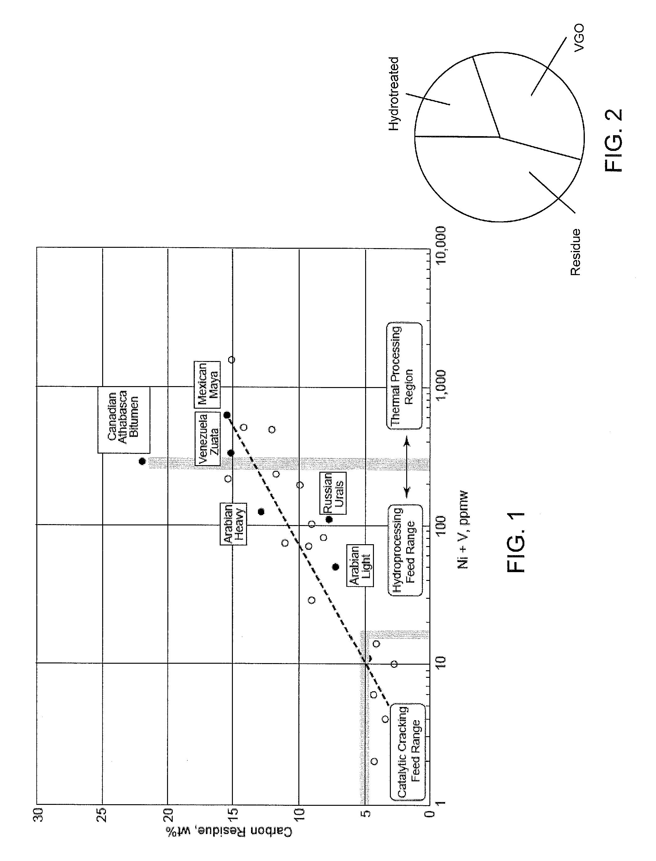
[0015]As used herein, the term “crude oil” is to be understood to mean a mixture of petroleum liquids and gases, including impurities such as sulfur-containing compounds, nitrogen-containing compounds and metal compounds, as distinguished from fractions of crude oil. In certain embodiments the crude oil feedstock is a minimally treated light crude oil to provide a crude oil feedstock having total metals (Ni+V) content of less than 5 ppm and Conradson carbon residue of less than 5 wt %. A wider range of crude oil can be accommodated by the present process, including light grade crude oil with low coke formation tendency, in particular in embodiments in which heavy cycle oil and / or slurry oil is recycled to the downflow reactor processing the light fraction, whereby the recycle stream maintains heat balance of the operation.

Problems solved by technology

The low carbon content in the catalyst particles from the low boiling fraction downflow reactor is insufficient to provide the necessary heat.

Method used


Image

  • Process for high severity catalytic cracking of crude oil
  • Process for high severity catalytic cracking of crude oil
  • Process for high severity catalytic cracking of crude oil

Examples


example 1

[0047]Using the process disclosed herein in which the feedstock is fractioned into a low boiling fraction and a high boiling fraction, the crude oil feedstream was fractioned at a cut point of 300° C. Each fraction was sent to separate downers of a dual downer configuration for catalytic cracking at a cracking temperature of 600° C. in both downers. Each downer was operated at a catalyst-to-oil ratio of 31. The gasoline yield was 45.8 wt % for the heavy fraction and 54.2 wt % for the light fraction.

[0048]Overall product yields for both the comparative operation and the new operation are in Table 1, in which the products in the dual downer configuration were recombined.

[0049]

TABLE 1Product Yields, wt %Single DownerDual DownerProductsProducts, Recombined(Comparative 1)(Example 1)Ethylene3.6%3.6%Propylene13.1%13.5%Butene9.4%9.0%Dry Gas5.5%5.5%Gasoline47.9%47.2%LCO13.9%15.4%HCO2.8%3.5%Coke2.8%2.5%

example 2

[0051]Using the process disclosed herein in which the feedstock is fractioned into a low boiling fraction and a high boiling fraction, the crude oil feedstream was fractioned at a cut point of 300° C. Each fraction was sent to separate downers of a dual downer configuration for catalytic cracking at a cracking temperature of 600° C. in both downers. Each downer was operated at a catalyst-to-oil ratio of 20. Product yields for both the comparative operation and the new operation are in Table 2, in which the products in the dual downer configuration were recombined.

[0052]

TABLE 2Product Yields, wt %Single DownerDual DownerProductsProducts, Recombined(Comparative 2)(Example 2)Ethylene3.2%3.0%Propylene11.6%11.7%Butene8.6%8.3%Dry Gas5.2%4.9%Gasoline47.5%48.9%LCO16.7%17.1%HCO3.8%4.2%Coke2.4%2.2%

example 3

[0053]Using the process disclosed herein in which the feedstock is fractioned into a low boiling fraction and a high boiling fraction, the crude oil feedstream was fractioned at a cut point of 300° C. Each fraction was sent to separate downers of a dual downer configuration for catalytic cracking. The downer for the heavy fraction was operated at a cracking temperature of 600° C. and a catalyst-to-oil ratio of 31 and the downer for the light fraction was operated at a cracking temperature of 640° C. and a catalyst-to-oil ratio of 32. Product yields for both the comparative operation (comparative example 1) and the new operation are in Table 3, in which the products in the dual downer configuration were recombined.

[0054]

TABLE 3Product Yields, wt %Single DownerDual DownerProductsProducts, Recombined(Comparative 1)(Example 3)Ethylene3.6%5.2%Propylene13.1%15.8%Butene9.4%10.3%Dry Gas5.5%8.5%Gasoline47.9%43.1%LCO13.9%13.1%HCO2.8%3.4%Coke2.8%2.5%

[0055]It is observed that at the same cracki...


PUM

PropertyMeasurementUnit
temperatureaaaaaaaaaa

Abstract

In an FCC process and system, a whole crude oil feedstock is directly converted into light olefins and other products. The feed is separated into a high boiling fraction and a low boiling fraction, and each fraction is processed in separate FCC downflow reactors. The catalyst, combined from both downflow reactors, is regenerated in a common vessel. The low carbon content in the catalyst particles from the low boiling fraction downflow reactor is insufficient to provide the necessary heat. By combining catalyst particles from the high boiling fraction having high carbon content helps to provide additional heat for regeneration.

Description

RELATED APPLICATIONS[0001]This application claims priority to provisional patent application number U.S. Ser. No. 61 / 716,051 filed Oct. 19, 2012, the contents of which are incorporated herein by reference.BACKGROUND OF THE INVENTION[0002]1. Field of the Invention[0003]The present invention relates to a fluidized catalytic cracking process to produce petrochemicals such as olefins and aromatics and improved quality distillate product.[0004]2. Description of Related Art[0005]Olefins (i.e., ethylene, propylene, butylene and butadiene) and aromatics (i.e., benzene, toluene and xylene) are basic building blocks which are widely used in the petrochemical and chemical industries. Thermal cracking, or steam pyrolysis, is a major type of process for forming these materials, typically in the presence of steam, and in the absence of oxygen. Feedstocks for steam pyrolysis can include petroleum gases and distillates such as naphtha, kerosene and gas oil. The availability of these feedstocks is u...

Claims


Application Information

Patent Timeline
Patent Type & Authority Patents(United States)
IPC IPC(8): C10G51/06C10G11/18
CPCC10G51/06C10G11/18C10G11/182C10G2300/201C10G2300/205C10G2300/708
Inventor BOURANE, ABDENNOURAL-GHRAMI, MUSAED SALEMABBA, IBRAHIM A.XU, WEISHAIK, KAREEMUDDIN M.
Owner SAUDI ARABIAN OIL CO
Why Eureka
Eureka Blog
Learn More