Surface-modified cyanide-based transition metal compounds

a transition metal and surface modification technology, applied in the field of surface-modified cyanide-based transition metal compounds, can solve the problems of less attractive anode active materials, low production efficiency, and low fade rate of electrodes, and achieve the effects of improving air stability, improving fade capacity loss, and good air stability

Active Publication Date: 2016-03-29
NATRON ENERGY INC
View PDF4 Cites 9 Cited by
  • Summary
  • Abstract
  • Description
  • Claims
  • Application Information

AI Technical Summary

Benefits of technology

[0015]Embodiments of surface modified cyanide-bridged coordination polymers of the present invention exhibit very good air stability. In some embodiments, a surface oxidation of particles of these materials, upon exposure to air, was negligible even after 60 hours. Comparisons between exposed and unexposed materials to air shows that there is no difference between their electrochemical performances and that there i

Problems solved by technology

However, many challenges must be have addressed before cyanide-based transition metal compounds may be safely, economically and used in an energy efficiently manner in an anode, especially in an anode operated in an aqueous electrolyte cell.
Relatively rapid fade rates of the electrode, as well as difficulties in processing and handling the materi

Method used


Image

  • Surface-modified cyanide-based transition metal compounds
  • Surface-modified cyanide-based transition metal compounds
  • Surface-modified cyanide-based transition metal compounds

Examples


example 1

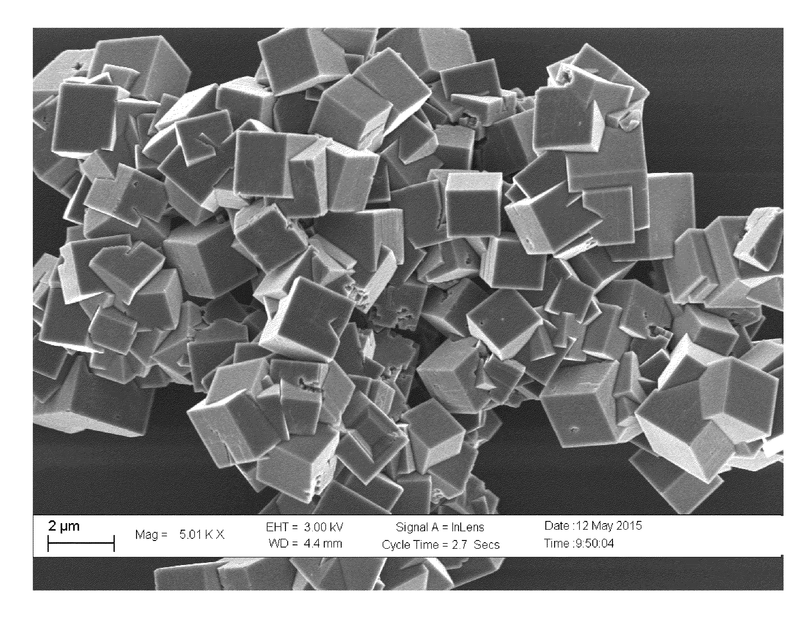
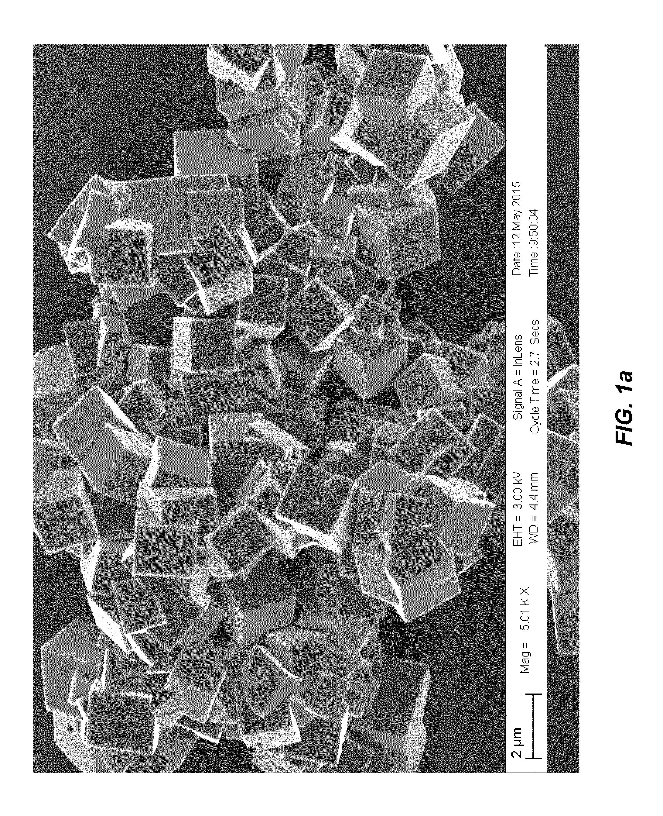
[0078](Product 1a)—To a stirred solution of manganese chloride tetrahydrate (23.75 g, 120.0 mmoles) in deaerated water (120 g), a solution of sodium cyanide (19.2 g, 392.0 mmoles) in deaerated water (90 g) was rapidly added over 1.0 min. under inert atmosphere of nitrogen (oxygen <0.1 ppm). The resulting mixture was stirred for an additional hour and then filtered over a 0.45 micron filter. The resulting blue powder was washed with deaerated water (50 ml), rinsed with deaerated methanol (200 ml) and dried under vacuum to give 19.7 g of a blue powder.

example 2

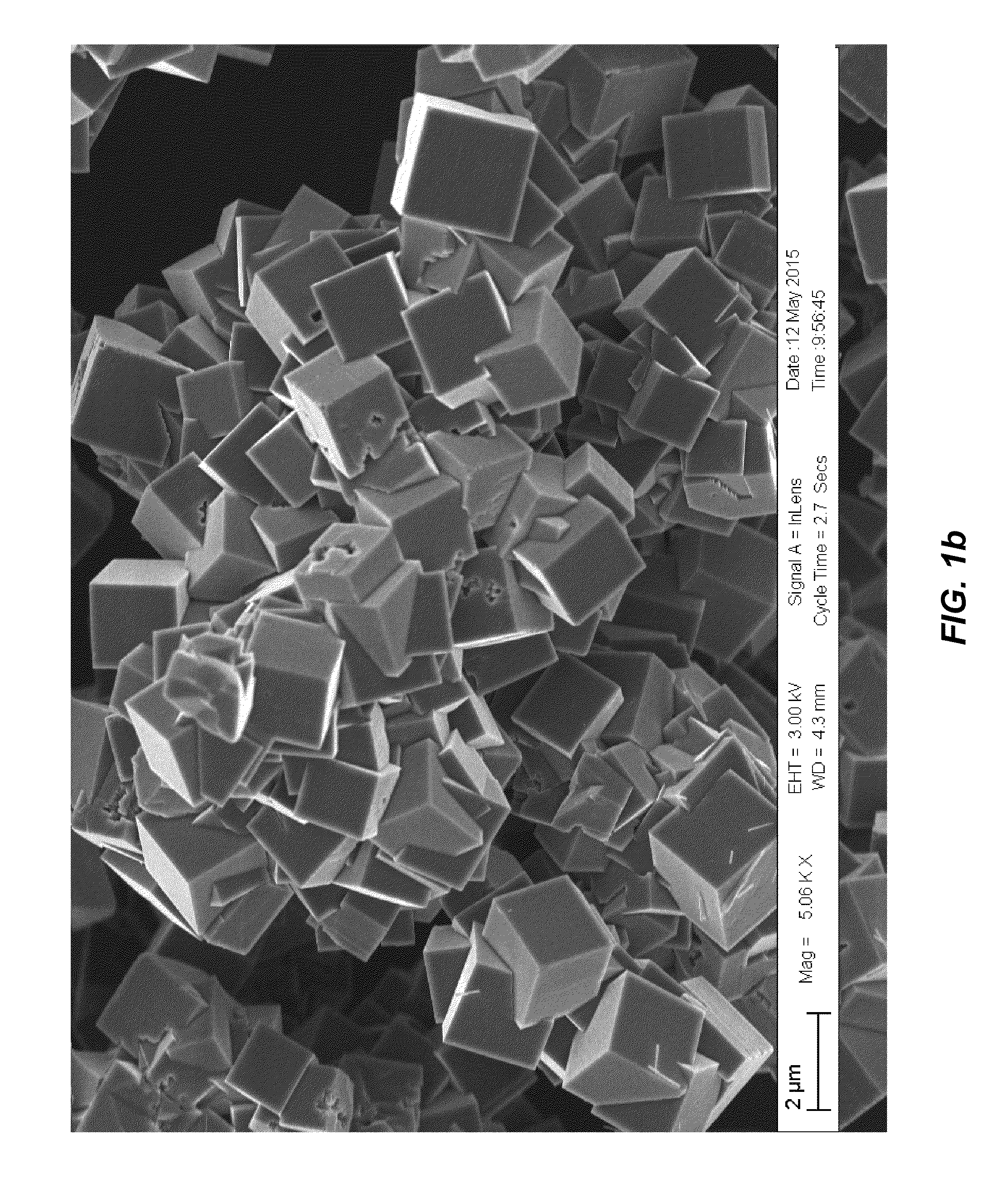
[0079](Product 2a)—To a stirred solution of manganese sulfate monohydrate (20.28 g, 120.0 mmoles) in deaerated water (120 g), a solution of sodium cyanide (19.2 g, 392.0 mmoles) in deaerated water (100 g) was rapidly added over 1.0 min. under inert atmosphere of nitrogen (oxygen <0.1 ppm). The resulting mixture was stirred for an additional hour and then filtered over a 0.45 micron filter. The resulting blue powder was washed with deaerated water (50 ml), rinsed with deaerated methanol (200 ml) and dried under vacuum to give 20.0 g of a blue powder.

example 3

[0080](Product 3a)—To a stirred solution of manganese acetate tetrahydrate (29.4 g, 120.0 mmoles) in deaerated water (120 g), a solution of sodium cyanide (19.2 g, 392.0 mmoles) in deaerated water (100 g) was rapidly added over 1.0 min. under inert atmosphere of nitrogen (oxygen <0.1 ppm). The resulting mixture was stirred for an additional hour and then filtered over a 0.45 micron filter. The resulting blue powder was washed with deaerated methanol (250 ml) and dried under vacuum to give 20.0 g of a blue powder.


PUM


Abstract

A system, method, and articles of manufacture for a surface-modified transition metal cyanide coordination compound (TMCCC) composition, an improved electrode including the composition, and a manufacturing method for the composition. The composition, compound, device, and uses thereof according to AxMn(y-k)Mjk[Mnm(CN)(6-p-q)(NC)p(Che)rq]z.(Che)rw(Vac)(1-z).nH2O (wherein Vac is a Mn(CN)(6-p-q)(NC)p(Che)rq vacancy); wherein Che is an acid chelating agent; wherein: A=Na, K, Li; and M=Mg, Al, Ca, Sc, Ti, V, Cr, Fe, Co, Ni, Cu, Zn, Ga, Pd, Ag, Cd, In, Sn, Pb; and wherein 0<j≦4; 0≦k≦0.1; 0≦(p+q)<6; 0<x≦4; 0≦y≦1; 0<z≦1; 0<w≦0.2; 0<n≦6; −3≦r≦3; and wherein: x+2(y−k)+jk+(m+(r+1)q−6)z+wr=0.

Description

STATEMENT REGARDING FEDERALLY SPONSORED RESEARCH OR DEVELOPMENT[0001]This invention was made with government support under ARPA-E Award No. DE-AR000300 With Alveo Energy, Inc., awarded by DOE. The government has certain rights in the invention.FIELD OF THE INVENTION[0002]The present invention relates generally to environmental stability of materials useful in electrochemical devices, and more specifically, but not exclusively, to compositions, articles of manufacture, and methods for manufacture of environmentally stabilized electrode active materials, for example stabilization of air sensitive anode active transition metal cyanide coordination compound (TMCCC) materials.BACKGROUND OF THE INVENTION[0003]The subject matter discussed in the background section should not be assumed to be prior art merely as a result of its mention in the background section. Similarly, a problem mentioned in the background section or associated with the subject matter of the background section should no...

Claims


Application Information

Patent Timeline
IPC IPC(8): C01C3/11C01C3/12H01M4/36H01M4/60H01M4/58
CPCH01M4/364H01M4/60H01M4/58C01C3/11C01C3/12C01G45/006H01M10/05H01M10/36Y02E60/10C07F13/00
Inventor MOTALLEBI, SHAHROKHWESSELLS, COLIN, DEANEVALENCIA, CHRISTIAN
Owner NATRON ENERGY INC
Why Eureka
Try Eureka