Piston-tube electrostatic microactuator

a microactuator and pipe-tube technology, applied in the field of microactuators, can solve the problems of high power consumption and large size, difficult fabrication, sensitive to temperature, etc., and achieve the effect of reducing the gas damping

Active Publication Date: 2016-04-05
SHEBA MICROSYST INC
View PDF9 Cites 22 Cited by
  • Summary
  • Abstract
  • Description
  • Claims
  • Application Information

AI Technical Summary

Benefits of technology

[0017](2) The piston-tube configuration significantly reduces the gas damping effects between the actuator electrodes, which is an inherent issue of the cavity-tooth configuration actuators listed previously. That is because no gas is trapped between the pistons and the tubes wh

Problems solved by technology

The electromagnetic actuators provide large stroke and high output force; nevertheless, they are known to have a number of disadvantages such as high power consumption and large size [7][4].
Although piezoelectric actuators provide high output force, they are sensitive to temperature and are difficult to fabricate[1][8].
However, it is challenging to design electrostatic actuators that can simultaneously provide high output force, large out-of-plane stroke and while maintaining a low voltage [10].
Due to the complexity of the structure of the rotor of this actuator, an undesirable tilt occurs during the translation of the lens when it is actuated by a number of similar actuators.
It works on the repulsive force principle, and the rotor of the actuator achieves an 86 μm vertical deflection at 200 V based on a rotational stroke at each of the four edges of the actuator which is then amplified using a cantilever beam; however, it provides a low output torque due to use of an amplification mechanism and to the small area of the fingers used to generate the force.
A translational VCD actuator, developed by V. Milanovic et al., achieved a translation stroke of 15 μm at 140 V. The actuator is fabricated using a Direct Reactive Ion Etching (DRIE) of an SOI wafer which enables the fabrication of large height electrodes; however, it provides a low output force as the comb electrode configuration is not area-efficient in terms of overall electrode capacitance.
A limitation of this actuator is that the tooth-cavity configuration requires the rotor and the stator of the actuator to be fabricated separately.
The fabricated rotor and stator wafers are then bonded together which may lead to a misalignment of sub-microns size between the upper and lower electrodes.
The cavity-tooth configuration also leads to gas damping effect between the comb electrodes as gas is trapped between the to

Method used


Image

  • Piston-tube electrostatic microactuator
  • Piston-tube electrostatic microactuator
  • Piston-tube electrostatic microactuator

Examples


embodiment 1

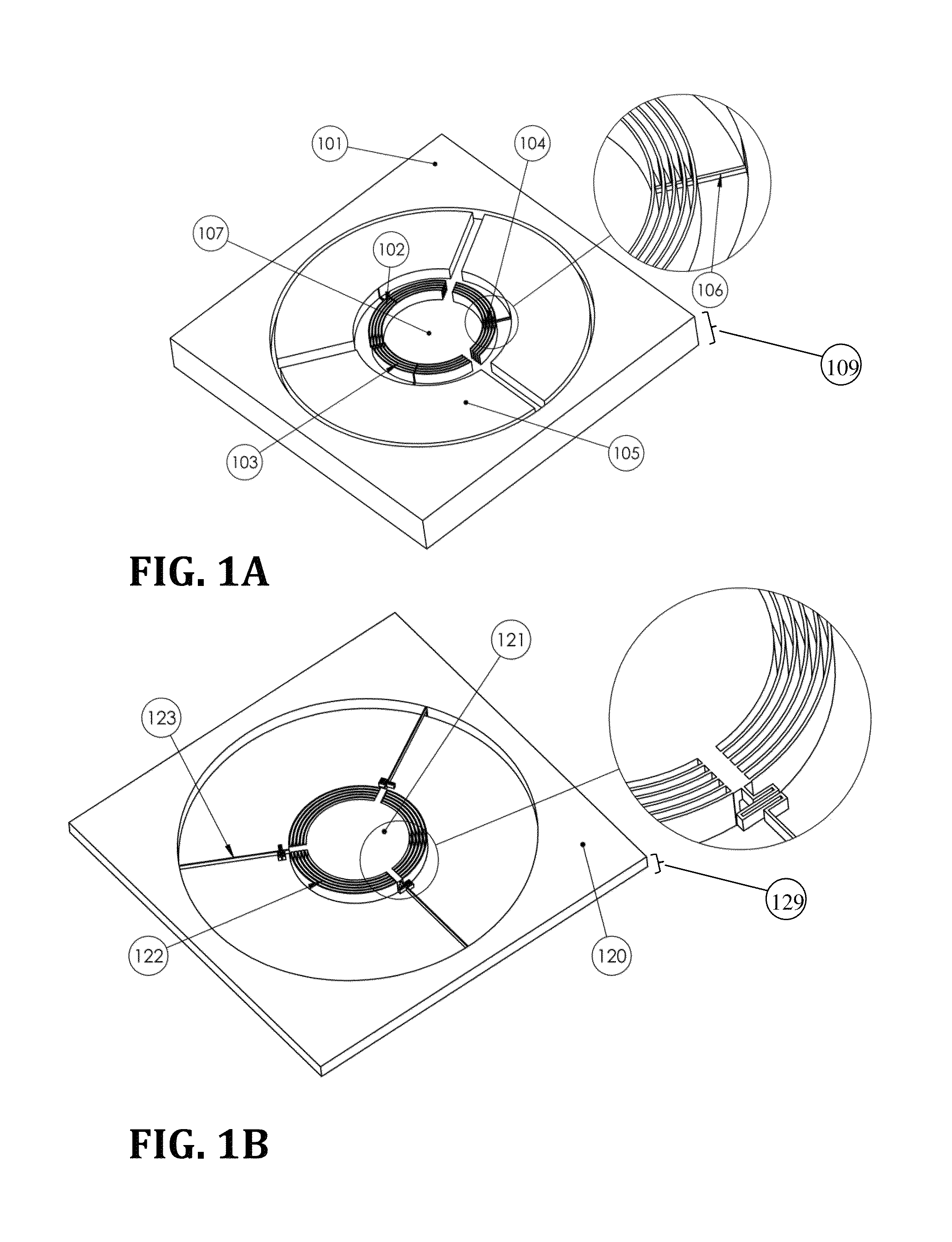
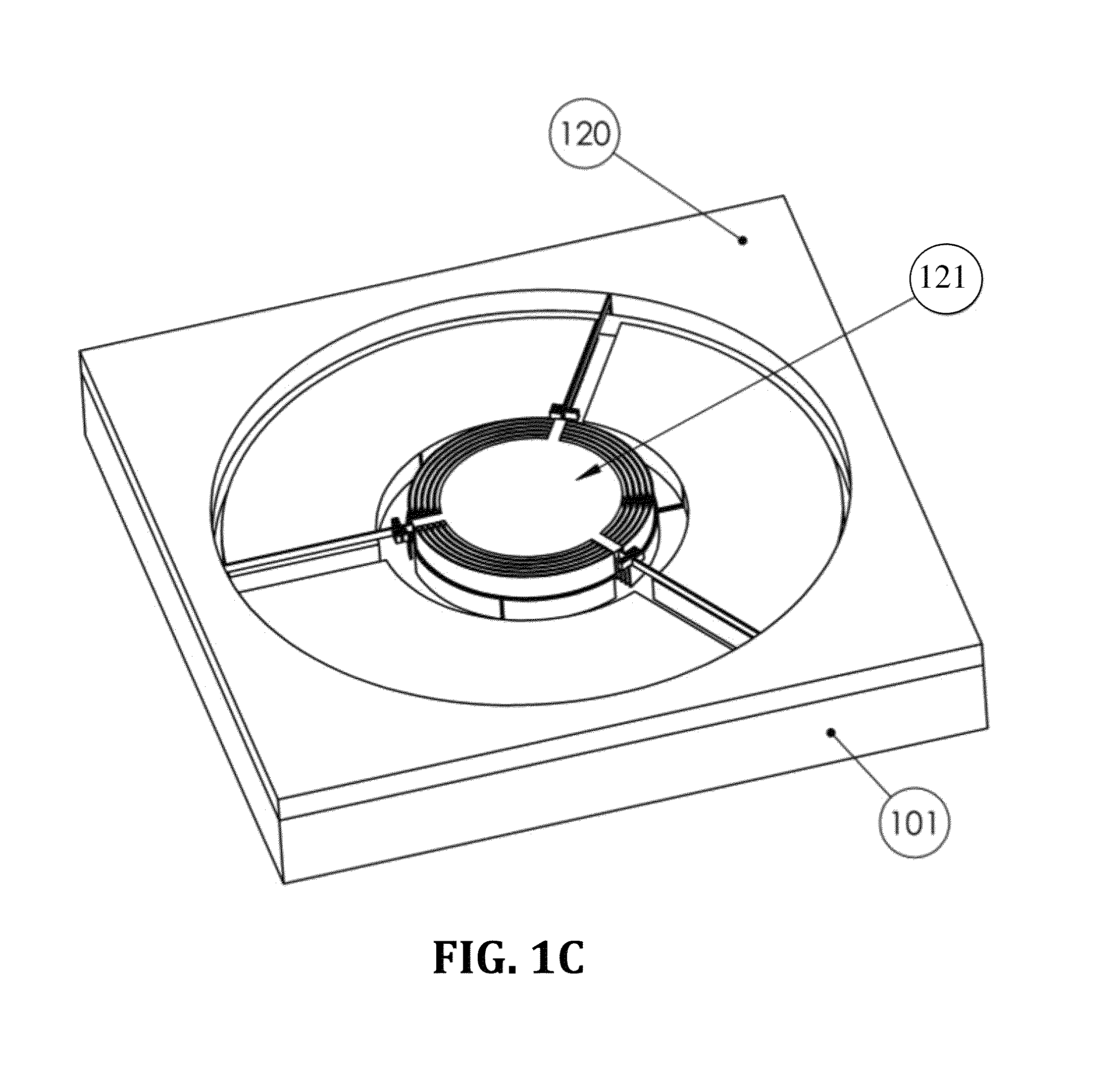
[0046]A first embodiment of the present invention (3-DOF MEMS electrostatic actuator) is illustrated in FIG. 1. The actuator comprises of a fixed structure, as illustrated in FIG. 1A, that comprises of a plurality of co-centric arc-shaped pistons 102, 103, 104, fabricated in the thickness 109 of a Si wafer 101. The actuator further comprises of a moving structure that comprises of a plurality of co-centric arc-shaped open tubes 122 (FIG. 1B). The tubes are sized and designed to receive the pistons of the fixed structure.[0047]The arc-shaped pistons are divided into three groups 102, 103, 104 that are arranged at 120°. Each group forms one stator of the actuator The pistons are vertically aligned with the arc-shaped open tubes 122 in the rotor. During the actuation, the pistons enter into the tubes and they inter-digitate during the actuation. The three stators 102, 103, 104 are electrically isolated from one another by utilizing the Buried Oxide (BOX) layer 107 of the SOI wafer. How...

embodiment 2

[0051]Another embodiment of the present actuator is illustrated in FIG. 2. In this embodiment the piston and tubes are aligned radially. The electrodes of the stator 201 and the rotor 225 are arranged in such a way that reduces changes in the gap 126 during rotation. The pistons 204, 205, 206, 207 in this embodiment are fabricated in a Si wafer 201, as plurality of pistons extending vertically upward from the bottom surface of the Si wafer 202, illustrated in FIG. 2A, extend radially from the inside to the outside periphery of the actuator. In this embodiment, the pistons are divided into four groups 204, 205, 206, 207, each being a stator. Similarly, the open tubes are fabricated in another Si wafer 225, as illustrated in FIG. 2B. The open tubes are also fabricated in four different groups 226, 227, 228, 229, that make the rotor of the actuator. The tubes are fabricated in the thickness of the wafer 225 around an actuator plate 222. The rotors are connected to the outer edges of th...

embodiment 3

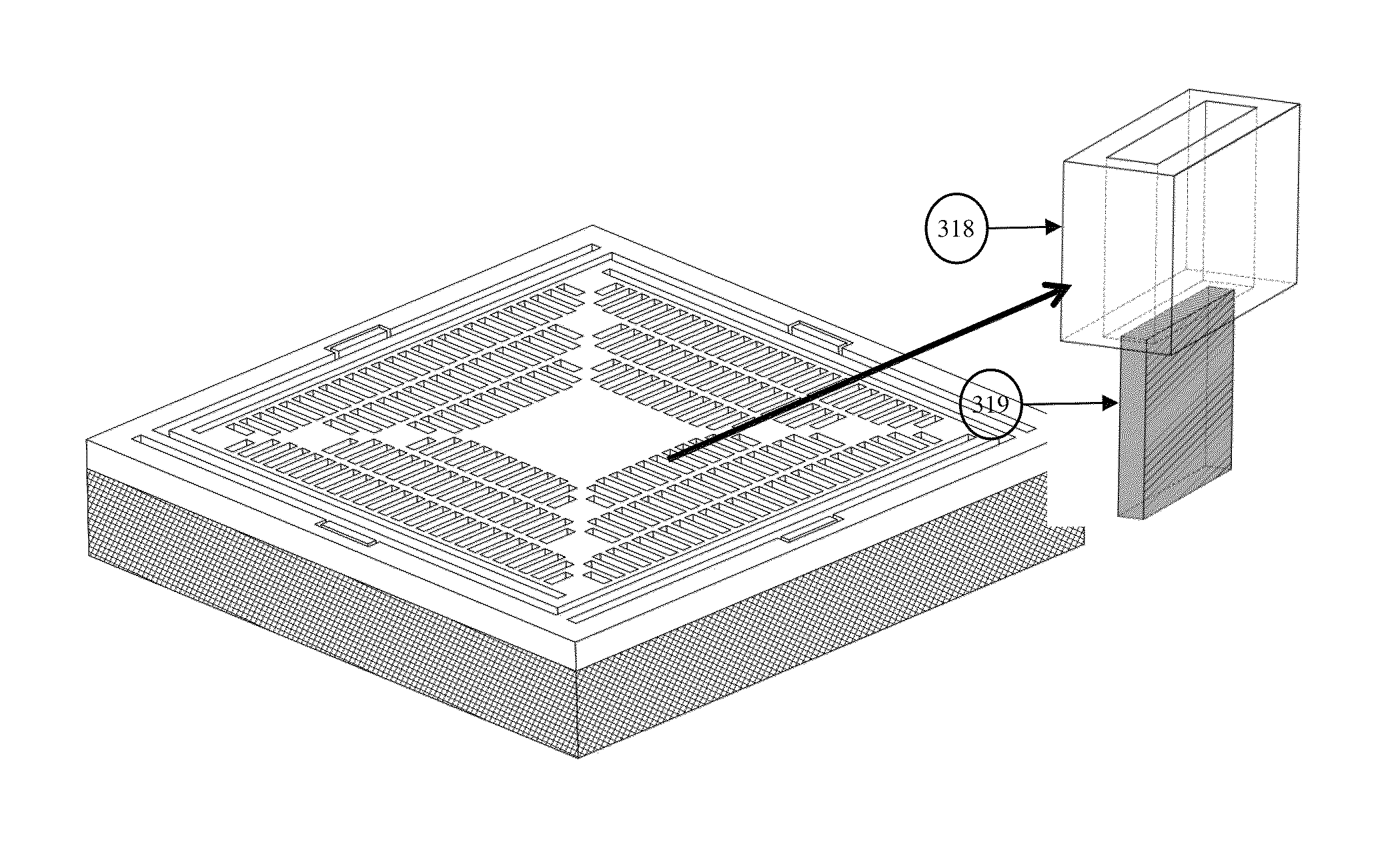
[0052]Another embodiment of the actuator is illustrated in FIG. 3. The subarray of pistons 304, 305, 306, 307 in this embodiment have rectangular cross-sections, and they are etched inside the base plate 301. This plate is fixed and it is therefore the stator of the actuator. A supporting frame 302 is kept around the pistons to later attach the rotor plate to. The base plate has a thickness 309A and the pistons have a length (height) 309B. Pistons extend vertically upward from the bottom of the base plate where the insulating layer 303 is located. The piston length 309B is smaller than the thickness of the plate 309A. In this embodiment, the pistons are made in four groups, each group comprising of three rows of pistons, extending horizontally along the two in-plane x and y axes The pistons in each stator are electrically connected to each layer through a small thickness layer 308. The pistons in each subarray are electrically insulated from other subarrays. It would be readily appa...


PUM


Abstract

A three-degrees-of-freedom MEMS electrostatic piston-tube actuator is disclosed. The actuator comprises two structures. A structure that comprises a plurality of fixed piston-like electrodes that are attached to a base, and form the stator of the actuator. A second structure that comprises a plurality of moving tube-like electrodes that are attached to the body of the upper structure and form the rotor of the actuator. The rotor is attached to the stator through a mechanical spring. The rotor of the actuator provides a 3-DOF motion, comprising vertical translation and bi-axial rotation about the axes of the structures. The present piston-tube actuator utilizes a configuration that enables the use of wide area electrodes, and therefore, provides a high output force enabling translation of the rotor or a high output torque enabling rotation of the rotor.

Description

FIELD OF THE INVENTION[0001]The invention relates to the field of microactuators that provide high force, large out-of-plane translation stroke and / or bi-axial rotation.BACKGROUND OF THE INVENTION[0002]Large out-of-plane translation and high output force microactuators have a wide range of applications in adaptive optics and in micro robotics. In adaptive optics, they are used for auto-focus [1] and Optical Image Stabilization (OIS) in miniature cameras [2] and deformable micromirrors [3]. For the auto-focus in phone cameras application, the actuator is required to translate a lens of 3 mg in mass along the optical axis for 80 μm [4]. The OIS in phone cameras requires a rotation of a lens barrel of 45 mg mass [2] for 1° about two axes in order to cancel any effects hand-shaking has on the images and recorded video. In micro robotics, large stroke and high output force actuators are used in micro assembly systems and microgrippers [5][6].[0003]Different micro actuation methods are in...

Claims


Application Information

Patent Timeline
IPC IPC(8): H02N1/00H02N1/08
CPCH02N1/006H02N1/002H02N1/008B81B2203/0136B81B3/0062B81B2203/053
Inventor BA-TIS, FAEZBEN-MRAD, RIDHA
Owner SHEBA MICROSYST INC
Why Eureka
Try Eureka