
Preparing color toner images with metallic effect

a technology of color toner and metallic effect, which is applied in the direction of thin material processing, electrographic process equipment, instruments, etc., can solve the problems of imperfect reproducibility of metallic hues, difficulty in reproducing gold tone through such a color mixture, and inability to readily incorporate metallic pigments, so as to enhance the electrostatic charging properties of metallic dry toner particles, enhance the uniform dispersion of non-conductive metal oxide particles, and enhance the effect of luster

Active Publication Date: 2016-04-26
EASTMAN KODAK CO
View PDF31 Cites 31 Cited by
  • Summary
  • Abstract
  • Description
  • Claims
  • Application Information

AI Technical Summary

Benefits of technology

The patent text describes a method for creating metallic-looking toner images on a receiver material. This is done by using special toner particles made from a mixture of metal oxide and a polymeric binder. The manufacturing process involves a melt extrusion process that can disperse the metal oxide particles evenly throughout the binder. By controlling the conditions during extrusion, breakage of the metal oxide particles can be minimized, resulting in a stronger metallic effect in the final printed image. The extruded material is also formed with a drawdown, which aligns the metal oxide particles in the same direction as the material is drawn, further enhancing the metallic effect.

Problems solved by technology

A significant problem is posed in the production of metallic hues that are imperfectly reproducible by a color mixture formed from the primary colors and black (such as CMYK noted above).
A gold tone is particularly difficult to reproduce by means of such a color mixture.
Common metallic pigments are typically conductive and not readily incorporated into toner particles without adversely affecting magnetic, electrical, or electrostatic properties.
However, the appearance of images obtained using metal halides can be adversely affected by oxidation (for example tarnishing or toning of metals) promoted by those metal halides making the metallic quality to be unattractive or it disappear completely.
This random orientation leads to a loss of metallic hue and causes a dark appearance when such toner particles are fixed (fused) to a receiver material using heated rollers.
Thus, the metallic pigments are outside the toner particles and can become detached from those toner particles during manufacture or mixing during development, resulting in non-homogeneity in the toner composition that can result in transfer and cleaning problems.
Porous toner particles provide certain advantages but may not be useful in every application due to their porosity.
This method limits the largest size that can be achieved for the formation of toner particles containing metallic pigments.
Bronze and aluminum powders have been used as pigments to provide metallic effects but they do not disperse well in polymeric toner particles.
Such pigments are also very fragile and easily broken during extrusion processes used to form polymeric toner particles.
These pigments are also generally conductive and can adversely affect the charging abilities of the polymeric toner particles.
However, this has not been readily achieved using known metallic toner particles because it has been difficult to introduce metallic particles into known dry toner particles.
There are various problems with known processes.
For example, it has been difficult to provide suitable metallic effects in toner images because in order to have high reflecting surface area.
Many reflective metallic particles are too easily broken into smaller particles during handling or manufacture of toner particles.
If the metallic particle size can be maintained, the size of the toner particles must be larger than is normally used in the industry, but larger toner particles are more difficult to fix (fuse) on receiver materials because of the low thermal conductivity associated with larger toner particles.

Method used

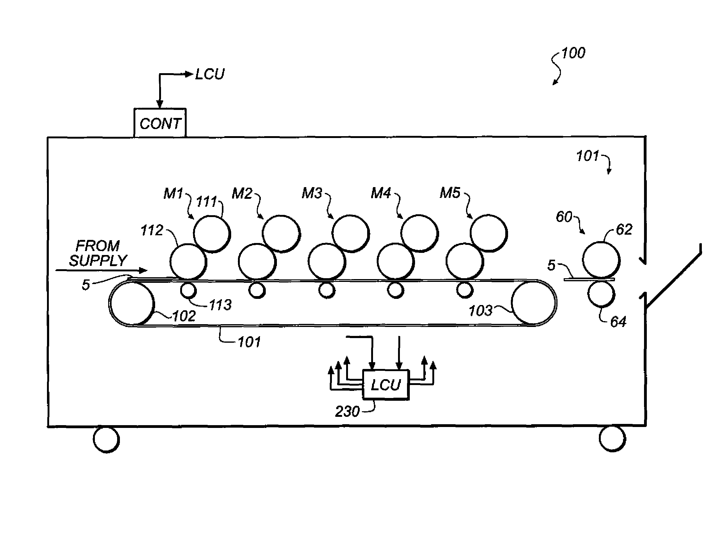

Image

  • Preparing color toner images with metallic effect
  • Preparing color toner images with metallic effect

Examples


Embodiment Construction

Definitions

[0063]As used herein to define various components of the metallic dry toner particles, polymers, non-conductive metal oxide particles, colorants, and other components, unless otherwise indicated, the singular forms “a,”“an,” and “the” are intended to include one or more of the components (that is, including plurality referents).

[0064]Each term that is not explicitly defined in the present application is to be understood to have a meaning that is commonly accepted by those skilled in the art. If the construction of a term would render it meaningless or essentially meaningless in its context, the term's definition should be taken from a standard dictionary.

[0065]The use of numerical values in the various ranges specified herein, unless otherwise expressly indicated otherwise, are considered to be approximations as though the minimum and maximum values within the stated ranges were both preceded by the word “about.” In this manner, slight variations above and below the state...


PUM


Abstract

A color toner image with a metallic effect can be prepared by forming one or more latent images and developing them with metallic dry toner particles and color toner particles. The developed color toner image can be transferred to a receiver material, and fixed to provide a color toner image with a metallic effect. The metallic dry toner particles have a polymeric binder phase and non-conductive metal oxide particles dispersed therein. Before fixing, the metallic dry toner particle has a mean volume weighted diameter (Dvol) 15-40 μm and the non-conductive metal oxide particles are present in an amount of at least 20-50 weight % based on total metallic dry toner particle weight. The ratio of the metallic dry toner particle Dvol to the average equivalent circular diameter (ECD) of the non-conductive metal oxide particles in the metallic dry toner particles is greater than 0.1 and up to and including 10.

Description

RELATED APPLICATION[0001]This is a Continuation-in-part of commonly assigned U.S. Ser. No. 13 / 462,111 filed May 2, 2012 by Tyagi, Lofftus, Granica, and Allen, now abandoned.FIELD OF THE INVENTION[0002]This invention relates to a method for using metallic dry toner particles that are designed to provide a metallic effect in the preparation of color toner images particularly in electrophotography.BACKGROUND OF THE INVENTION[0003]One common method for printing images on a receiver material is referred to as electrophotography. The production of black-and-white or color images using electrophotography generally includes the producing a latent electrostatic image by uniformly charging a dielectric member such as a photoconductive substance, and then discharging selected areas of the uniform charge to yield an imagewise electrostatic charge pattern. Such discharge is generally accomplished by exposing the uniformly charged dielectric member to actinic radiation provided by selectively act...

Claims


Application Information

Patent Timeline
Patent Type & Authority Patents(United States)
IPC IPC(8): G03G9/09G03G13/20G03G15/00G03G9/08G03G9/097
CPCG03G13/20G03G9/0819G03G9/09708G03G9/09725G03G15/6585Y10T428/24901
Inventor TYAGI, DINESHLOFFTUS, KEVIN D.GRANICA, LOUISEALLEN, RICHARD GEORGE
Owner EASTMAN KODAK CO
Learn More