
System and method for quantum information transfer between optical photons and superconductive qubits

a quantum information transfer and optical photon technology, applied in nanoinformatics, instruments, computing models, etc., can solve the problems of imposing a fundamental limit on the ability to distinguish different coherent states, limiting discrimination to have a finite minimum probability of error, and arbitrary state cannot be cloned

Active Publication Date: 2016-05-24
RAYTHEON BBN TECH CORP
View PDF2 Cites 42 Cited by
  • Summary
  • Abstract
  • Description
  • Claims
  • Application Information

AI Technical Summary

Benefits of technology

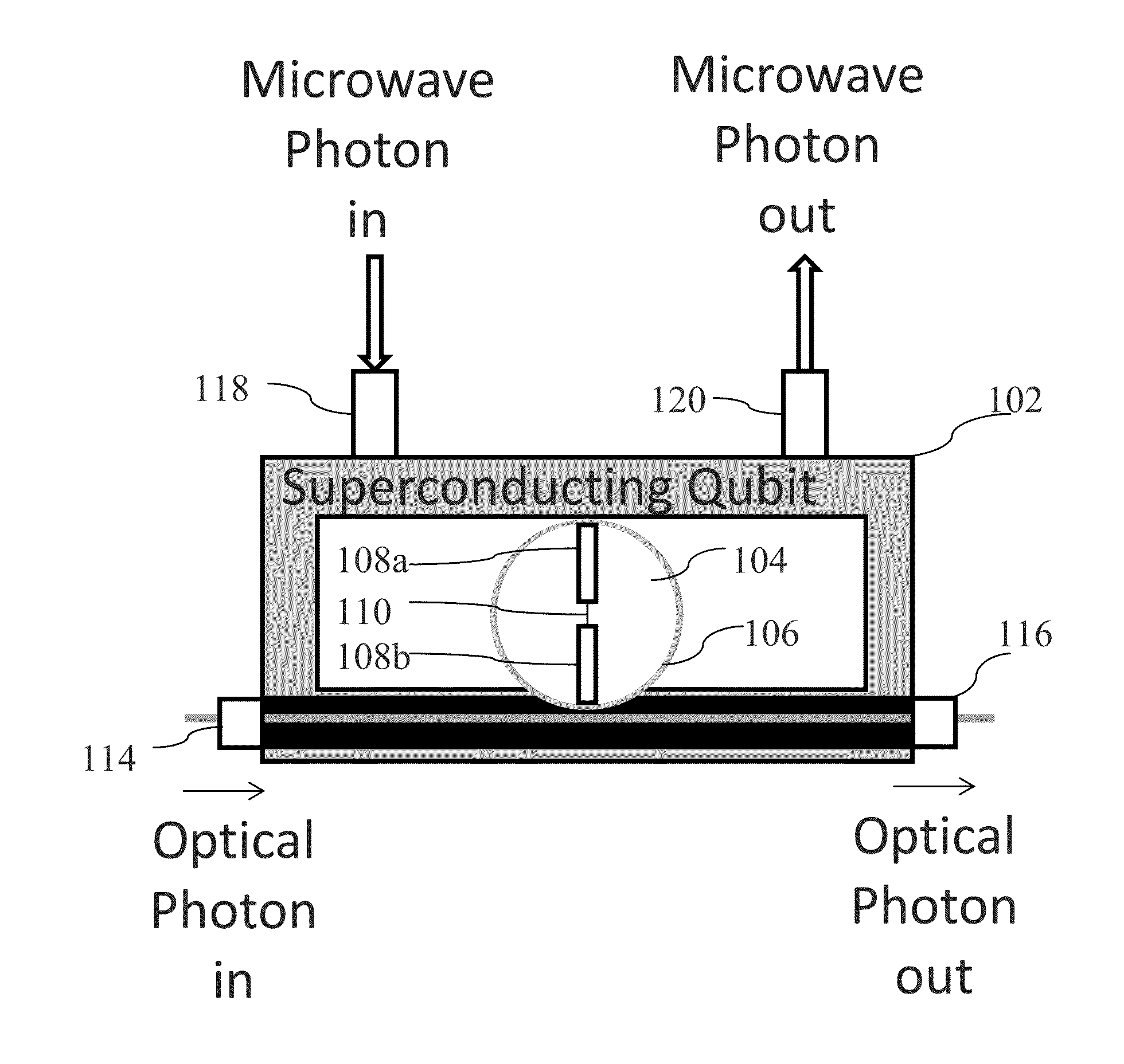
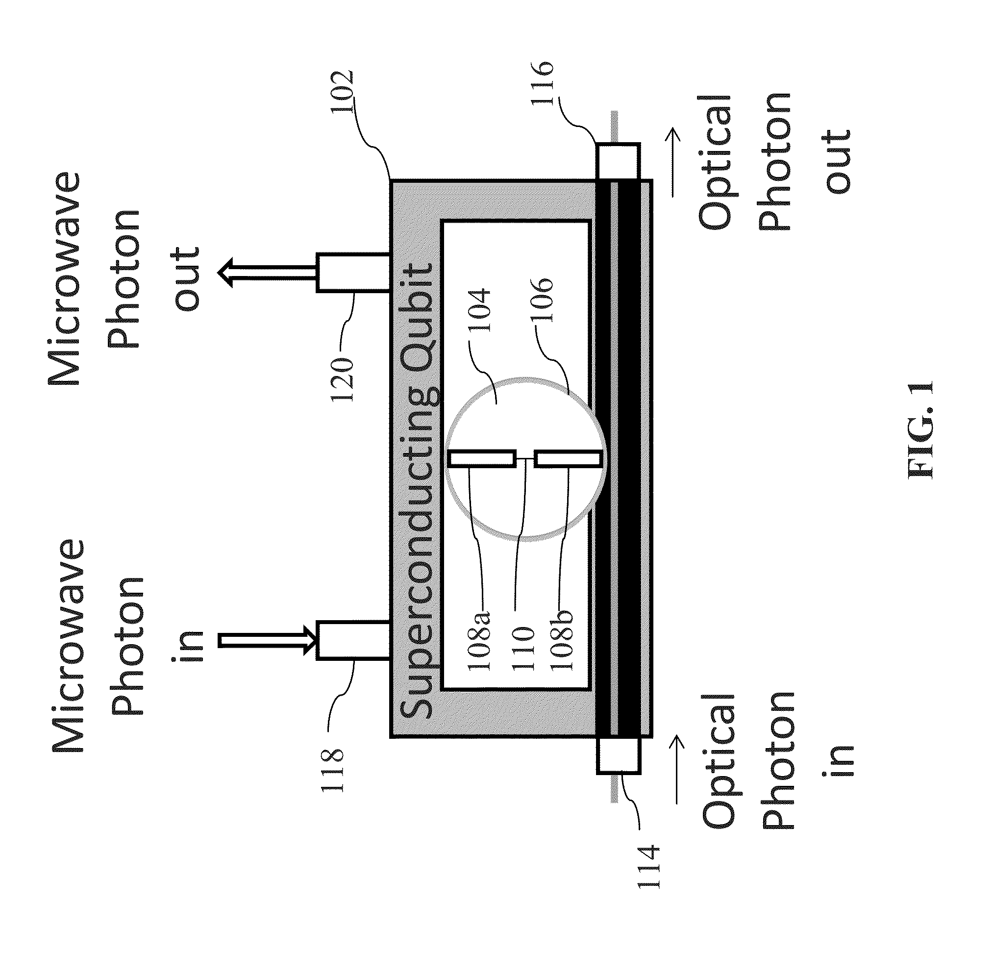
The present invention is an electro-optical system and method for exchanging quantum information between optical qubits and superconducting qubits. The system includes a superconductive microwave cavity, an electro-optical material positioned inside of the superconductive microwave cavity, and a superconductive qubit circuit formed on the electro-optical material including a superconductive qubit with two electrodes. The system can receive input optical photons and microwave photons and modulate their frequency with the state of the superconducting qubit using the electro-optic effect of the optical cavity. The method involves storing the received optical photons in an optical cavity, receiving optical pump signals, activating the electro-optic effect, and outputting the modulated optical photons. The invention has applications in quantum computing and communication.

Problems solved by technology

Furthermore, in quantum information, an arbitrary state cannot be cloned.
However, quantum mechanics imposes a fundamental limit on how well different coherent states can be distinguished, even with perfect detectors, and limits such discrimination to have a finite minimum probability of error.
However, quantum processing of qubits typically costly and challenging due to ever changing states of the qubits.

Method used


Image

  • System and method for quantum information transfer between optical photons and superconductive qubits
  • System and method for quantum information transfer between optical photons and superconductive qubits
  • System and method for quantum information transfer between optical photons and superconductive qubits

Examples


Embodiment Construction

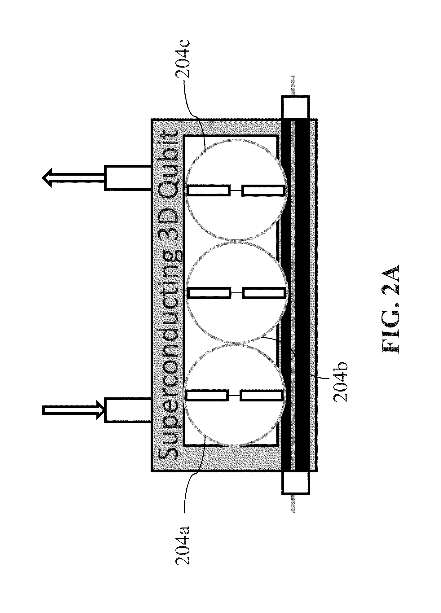
[0026]The present invention is directed to a method and an electro-optic system which can exchange quantum information between optical qubits at frequencies ranging from infrared to ultraviolet and superconducting qubits at microwave frequencies between DC to a few hundred GHz. In some embodiments, the present invention uses high-Q superconducting qubits (for example, three-dimensional (3D) qubits) fabricated on a nonlinear electro-optic (EO) material that forms a high-Q whispering gallery optical cavity. The use of such superconducting qubits allows an order of magnitude improvement in the achievable coherent coupling rate over previous proposals that use parallel-plate capacitors or coplanar waveguides. The stronger coupling according to the present invention translates directly into fast exchange of information, which is critical to high-fidelity quantum operations.

[0027]There are several advantages to using superconducting qubits in direct coupling to the optical qubits. First, ...


PUM


Abstract

An electro-optical system for exchanging quantum information between optical qubits and including a superconductive microwave cavity; an electro-optical material; a superconductive qubit circuit formed on the electro-optical material including a superconductive qubit; a dipole antenna, formed on the electro-optical material for directly coupling the superconductive qubit to the superconductive microwave cavity; an optical input for receiving input optical photons; a microwave input for receiving input microwave photons; and an optical output for outputting modulated optical photons, wherein a frequency and a phase of the optical photon is modulated with a state of the superconducting qubit by the dipole antenna.

Description

FIELD OF THE INVENTION[0001]The present invention relates to a system and method for quantum information transfer between optical photons (qubits) and superconductive qubits.BACKGROUND[0002]Quantum information is physical information that is held in the state of a quantum system. The unit of quantum information may be a qubit, a two-level quantum system. In contrast to discrete classical digital states, a two-state quantum system can be in a superposition of the two states at any given time. Unlike classical information, quantum information cannot be read without the state being disturbed by the measurement device. Furthermore, in quantum information, an arbitrary state cannot be cloned.[0003]Coherent states of light, such as those of laser light waveforms, are widely used for communication and sensing applications, so the optimal discrimination of coherent states, that is, the quantum states of light emitted by a laser, has immense practical importance. However, quantum mechanics i...

Claims


Application Information

Patent Timeline
Patent Type & Authority Patents(United States)
IPC IPC(8): H04B10/00B82Y10/00H04B10/2575H04B10/70G06N99/00
CPCH04B10/70B82Y10/00G06N99/002H04B10/2575G06N10/00
Inventor PAIK, HANHEE
Owner RAYTHEON BBN TECH CORP
Learn More