Oxy-fuel combustion system with closed loop flame temperature control

a combustion system and flame temperature control technology, applied in combustion control, furnaces, muffle furnaces, etc., can solve the problems of affecting the efficiency of the combustion process, and causing environmental harm, so as to improve the combustion process efficiency

Active Publication Date: 2016-05-31
JUPITER OXYGEN CORP
View PDF31 Cites 6 Cited by
  • Summary
  • Abstract
  • Description
  • Claims
  • Application Information

AI Technical Summary

Benefits of technology

[0012]The present invention relates to a control system for an oxy-fuel combustion process for use with a boiler or furnace which dynamically controls the flame temperature of each burner involved in the combustion process to dynamically maximize the flame temperature. The boiler or furnace used in conjunction with the combustion process in accordance with the present invention is configured with a radiant, i.e. line of sight, heat zone and a convective heat zone. By dynamically maximizing the flame temperature of the various burners within the boiler or furnace, the radiant heat transfer is optimized. By optimizing the radiant heat transfer within the boiler or furnace, the efficiency of the boiler or furnace is significantly improved.

Problems solved by technology

For example, a major disadvantage of air-fueled combustion systems is the production of green-house gasses, which are known to be harmful to the environment.
Another disadvantage of such air-fueled combustion processes relates to fuel efficiency.
In such air-fueled combustion processes, a considerable amount of fuel is expended to heat the nitrogen in the boiler or furnace.
Because of the vast amount of nitrogen in the boiler or furnace, a significant amount of heat and thus fuel are wasted heating the nitrogen in the boiler or furnace, which is processed and released as waste.
However, the improvements disclosed in these patents involve fixed variables in the combustion process, namely flame shape, and do not take into account other variables, such as the amount of fuel used in the combustion process.
However, dynamic variables in the combustion process, such as flame temperature, are also known to affect the efficiency of the oxy-fuel combustion process.

Method used


Image

  • Oxy-fuel combustion system with closed loop flame temperature control
  • Oxy-fuel combustion system with closed loop flame temperature control
  • Oxy-fuel combustion system with closed loop flame temperature control

Examples


Embodiment Construction

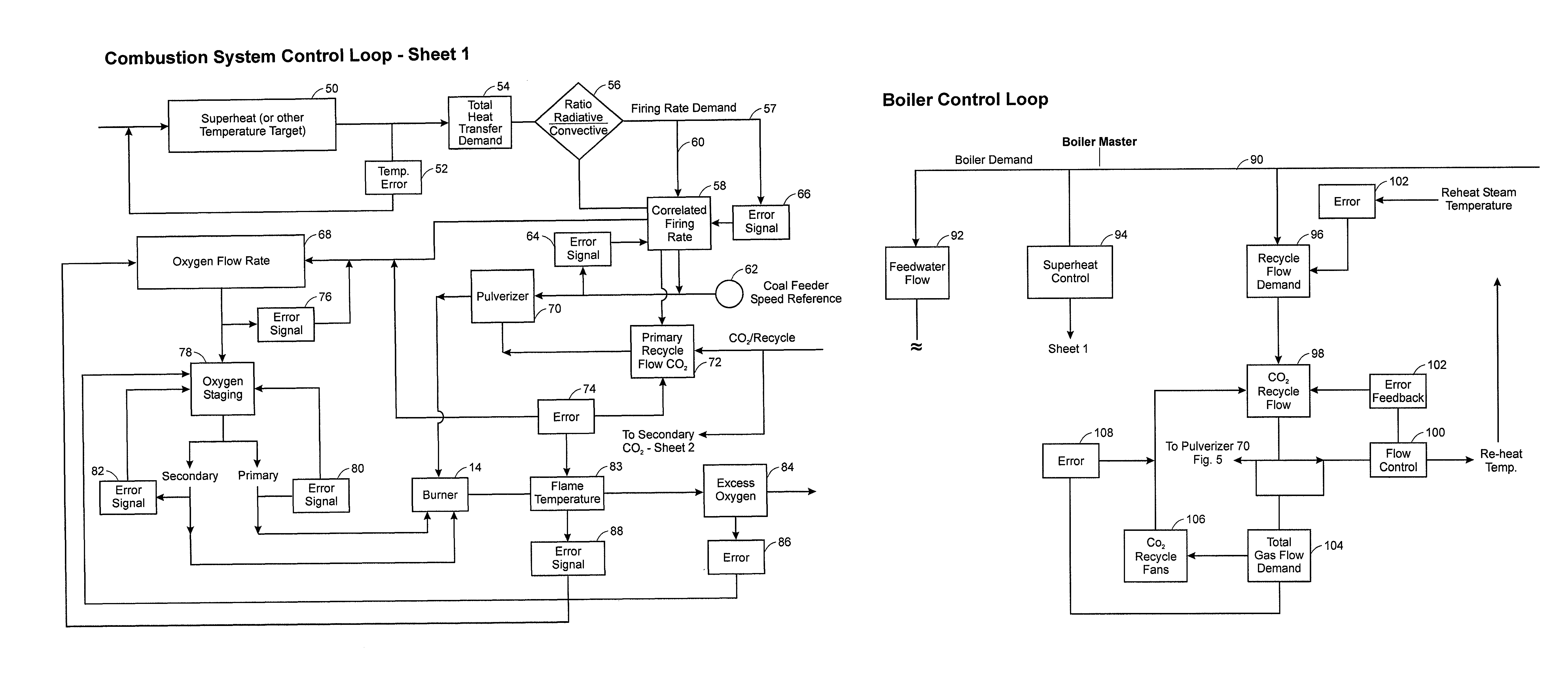
[0020]The present invention relates to a control system for an oxy-fuel combustion process which dynamically controls the flame temperature of each burner involved in the combustion process to dynamically maximize the flame temperature while maintaining the design, steam or process temperature and interior material temperatures. Although the combustion process in accordance with the present invention is described in terms of a boiler, the principles of the present invention are equally applicable to furnaces, for example, for processing aluminum while maintaining the designed aluminum melting or holding temperature or steam or process temperatures and internal material temperatures.

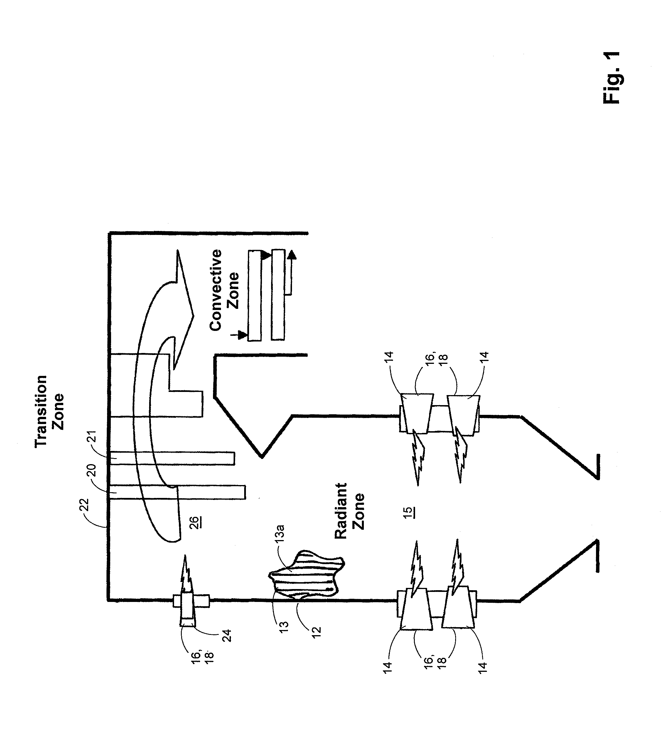
[0021]As will be discussed in more detail below, the boiler used in conjunction with the combustion process in accordance with the present invention is configured with a radiant, i.e. line of sight, heat zone and a convective heat zone. By dynamically maximizing the flame temperature of the various burner...


PUM


Abstract

A control system for an oxy-fuel combustion process is disclosed for use with a boiler or furnace which dynamically controls the flame temperature of each burner involved in the combustion process to dynamically maximize the flame temperature. The boiler or furnace used in conjunction with the combustion process in accordance with the present invention is configured with a radiant, i.e. line of sight, heat zone and a convective heat zone. By dynamically maximizing the flame temperature of the various burners within the boiler or furnace, the radiant heat transfer is optimized. By optimizing the radiant heat transfer within the boiler or furnace, the efficiency of the boiler or furnace is significantly improved.

Description

CROSS REFERENCE TO RELATED APPLICATIONS[0001]This application claims priority to and the benefit of U.S. Patent Application No. 61 / 096,106, filed on Sep. 11, 2008, hereby incorporated by reference.BACKGROUND OF THE INVENTION[0002]1. Field of the Invention[0003]The present invention relates to an oxygen fuel (oxy-fuel) combustion system and more particularly to combustion system for fossil fuels that utilizes oxygen for combustion that includes closed loop control of the flame temperature in order to maximize the radiation heat transfer of the combustion thereby optimizing the efficiency of combustion system while maintaining the design aluminum melting or holding temperature or steam or process temperature and interior material temperatures.[0004]2. Description of the Prior Art[0005]Combustion systems for fossil fuels, i.e carbon based fuels, which utilize oxygen for combustion in lieu of air relatively well known in the art. Examples of such systems are disclosed in International P...

Claims


Application Information

Patent Timeline
Patent Type & Authority Patents(United States)
IPC IPC(8): F23N1/02F22B37/10F27B5/14F27D17/00F27B1/26F23N5/00
CPCF23N5/00F23N1/02F23N1/022F23N2037/28F23N2237/28Y02E20/34
Inventor GROSS, DIETRICH M.PATRICK, BRIAN R.SCHOENFIELD, MARK
Owner JUPITER OXYGEN CORP
Why Eureka
Try Eureka