Reciprocating type porous medium gas burning metal smelting furnace

A porous medium and reciprocating technology, applied in furnaces, crucible furnaces, furnace components, etc., can solve the problems of high combustion efficiency and energy utilization, low pollution emissions, etc., and achieve high combustion efficiency and energy utilization, The effect of low pollution emission and high combustion intensity

Inactive Publication Date: 2011-11-16
ZHEJIANG UNIV
View PDF8 Cites 6 Cited by
  • Summary
  • Abstract
  • Description
  • Claims
  • Application Information

AI Technical Summary

Problems solved by technology

[0006] Aiming at the problems of large energy consumption and serious pollution discharge in the production process of gas-fired metal smelting furnaces, the invention adopts a new reciprocating porous medium combustion theory and technology, utilizes reciprocating flow porous medium heat storage to greatly recover waste heat, has high combustion efficiency and energy utilization rate, and reduces pollution Low emission and remarkable energy saving effect

Method used


Image

  • Reciprocating type porous medium gas burning metal smelting furnace
  • Reciprocating type porous medium gas burning metal smelting furnace
  • Reciprocating type porous medium gas burning metal smelting furnace

Examples


Embodiment 1

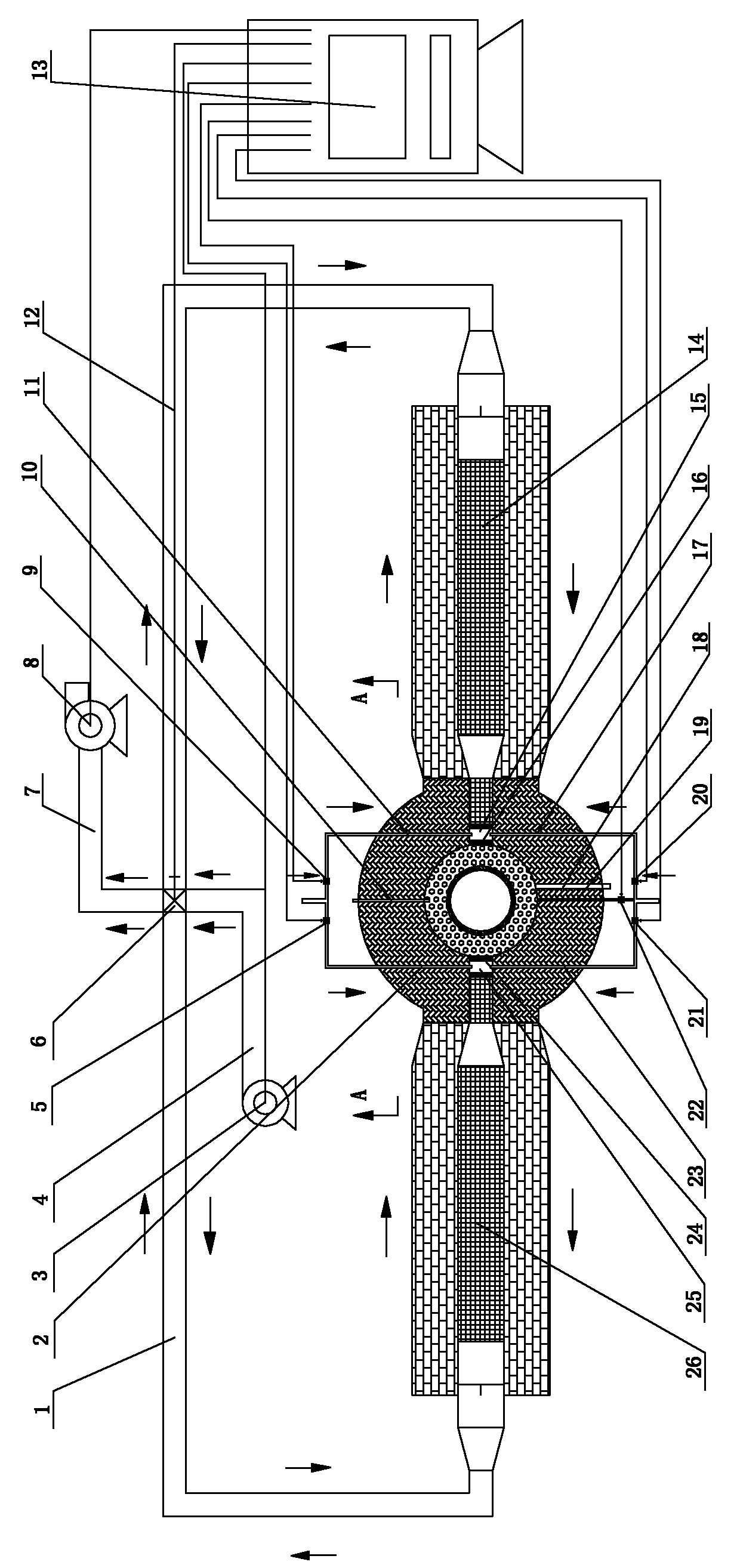
[0028] like figure 1 , the first air flue gas channel 1, the first gas inlet pipe 2, the blower 3, the air supply channel 4, the first gas control valve 5, the air flue gas reversing valve 6, the flue gas flow channel 7, the induced draft fan 8 , the second gas control valve 9, the thermocouple 10, the second gas inlet pipe 11, the second air flue flow channel 12, the controller 13, the second porous medium regenerator 14, the second gas high-temperature air mixing chamber 15 , the second gas air inlet perforated plate 16, the third gas inlet pipe 17, the flame detector 18, the high-energy electronic igniter 19, the third gas control valve 20, the fourth gas control valve 21, the ignition gas control valve 22, the fourth Gas inlet pipe 23 , first gas high temperature air mixing chamber 25 , first gas air inlet perforated plate 24 , first porous medium heat storage chamber 26 .

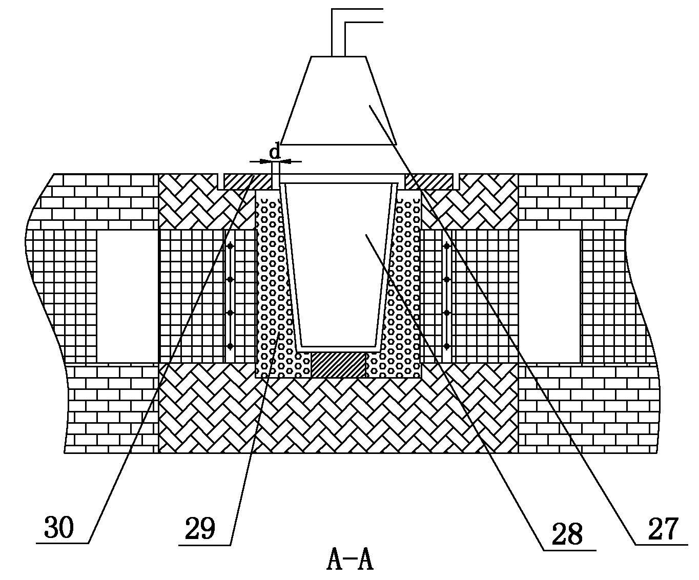
[0029] like figure 2 , Smelting gas removal device 27, metal holding container 28, combustion ch...

Embodiment 2

[0042] Refer to attached figure 1 , 2 , 5(a), 5(b):

[0043] The difference between this embodiment and Embodiment 1 is that the arrangement of the first porous medium heat storage chamber and the second porous medium heat storage chamber is arranged in the same direction, and the second porous medium heat storage chamber 14 and the first porous medium heat storage chamber The included angle β between the heat storage chambers 26≤20°.

[0044] The rest is the same.

Embodiment 3

[0046] Refer to attached figure 1 , 2 , 3, 4(a), 4(b):

[0047] The difference between the present embodiment and the first embodiment lies in that the air path setting of the periodically reversing air supply mechanism is different.

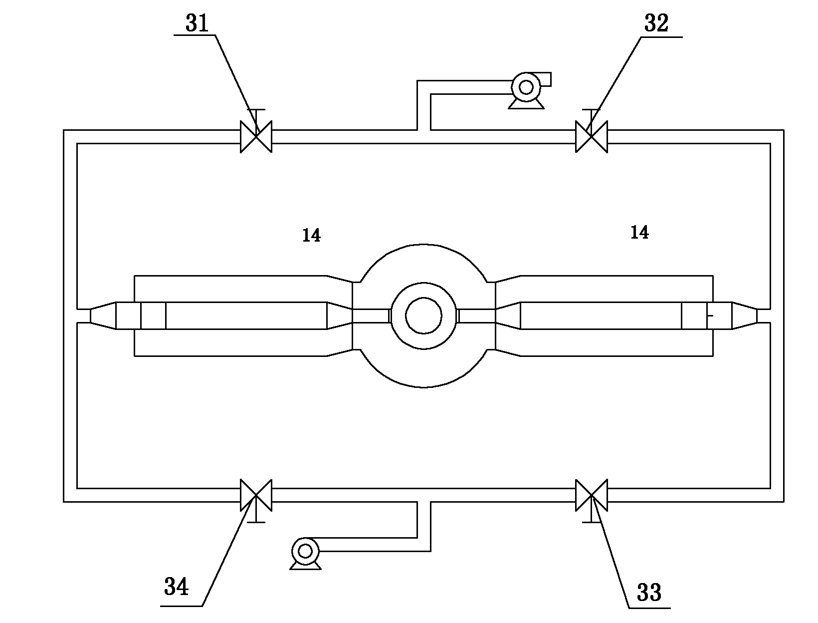
[0048] like image 3 As shown, the air and gas reversing valve 6 can adopt a 4-way control valve system. In the first half cycle, the second air and flue gas reversing valve 32 and the fourth air and flue gas reversing valve 34 are opened, and the first air and flue gas reversing valve 31 and the third air and flue gas reversing valve 33 are closed; The second air and smoke reversing valve 32 and the fourth air and smoke reversing valve 34 are closed, and the first air and smoke reversing valve 31 and the third air and smoke reversing valve 33 are opened.

[0049] The rest is the same.


PUM


Abstract

The invention discloses a reciprocating type porous medium gas burning metal smelting furnace which comprises a burning chamber and a metal accommodating container arranged in the burning chamber, wherein the burning chamber is connected with a first gas channel and a second gas channel, a first porous medium regenerative chamber is arranged in the first gas channel, and a second porous medium regenerative chamber is arranged in the second gas channel; the first gas channel and the second gas channel are evenly connected with a periodically reversing air supply mechanism, and the periodicallyreversing air supply mechanism comprises an air-smoke change valve controlled by a controller and is connected with an air supply channel and a smoke channel; and the combustion air and the high-temperature smoke are periodically and alternately reversed to flow through a porous medium high-efficient heat retainer, and the smoke waste heat is utilized to heat the combustion air. The metal smelting furnace provided with the invention has the advantages of short metal melting time, obvious energy-saving effect, high combustion efficiency, effective waste heat limited recycle, low energy consumption and low pollutant discharge.

Description

technical field [0001] This invention relates to metal melting furnaces. Background technique [0002] Crucible furnaces are mostly used for smelting non-ferrous metals such as copper, aluminum, and zinc alloys. The heating methods include coke heating, electromagnetic induction heating, and oil and gas combustion flame heating. The coke heating furnace has basically been eliminated due to the large environmental pollution and low energy utilization efficiency. The energy of the electromagnetic induction heating melting furnace comes from electricity, which is a high-grade energy. From the perspective of energy utilization, electromagnetic induction heating melting furnace is the process of converting high-grade energy electric energy into low-grade energy heat energy; in addition, due to power shortage, large one-time investment, and the need to avoid peak shifts, some enterprises, especially small enterprises The metal smelting furnace is mainly heated by a gas flame. F...

Claims


Application Information

Patent Timeline
Patent Type & Authority Applications(China)
IPC IPC(8): F27B14/10F27B14/14F27D17/00
Inventor 程乐鸣方梦祥王勤辉施正伦郑成航余春江周劲松王树荣高翔骆仲泱倪明江岑可法
Owner ZHEJIANG UNIV
Why Eureka
Try Eureka