
Manufacturing method of semiconductor structure

a manufacturing method and semiconductor technology, applied in the direction of semiconductor devices, basic electric elements, electrical apparatus, etc., can solve the problems of serious influence of residual capping layer on performance and function of mosfet devices, and the performance of mosfet devices will be affected accordingly, so as to improve the gain size uniformity of residual capping layers and improve the effect of residual capping layer problems

Active Publication Date: 2016-05-31
UNITED MICROELECTRONICS CORP
View PDF13 Cites 6 Cited by
  • Summary
  • Abstract
  • Description
  • Claims
  • Application Information

AI Technical Summary

Benefits of technology

The present invention provides a method for manufacturing a semiconductor structure. The method involves annealing the structure with oxygen before adding a capping layer. This treatment improves the uniformity of the capping layer and helps to reduce any residual capping layer issues. Additionally, the method can be used to create a layer of oxygen between a high-k dielectric layer and the semiconductor substrate, allowing for better control over the thickness of this layer.

Problems solved by technology

However, the thickness and the quality of the IL may be influenced by subsequent thermal processes, and the performance of the MOSFET device will be affected accordingly.
The capping layer has to be removed before the step of forming the metal gate, and the residual capping layer will seriously influence the performance and the function of the MOSFET device.

Method used


Image

  • Manufacturing method of semiconductor structure
  • Manufacturing method of semiconductor structure
  • Manufacturing method of semiconductor structure

Examples


Embodiment Construction

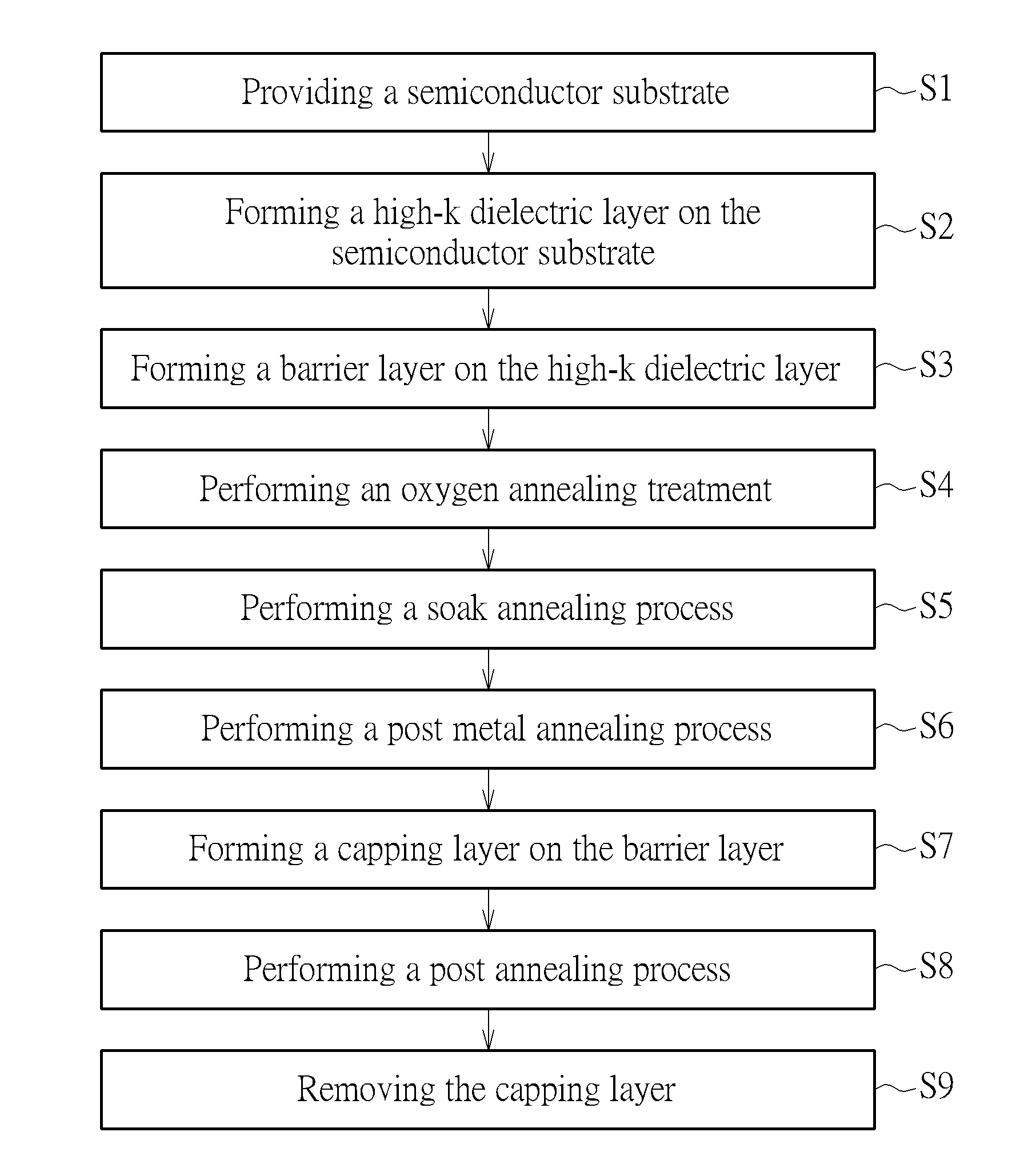
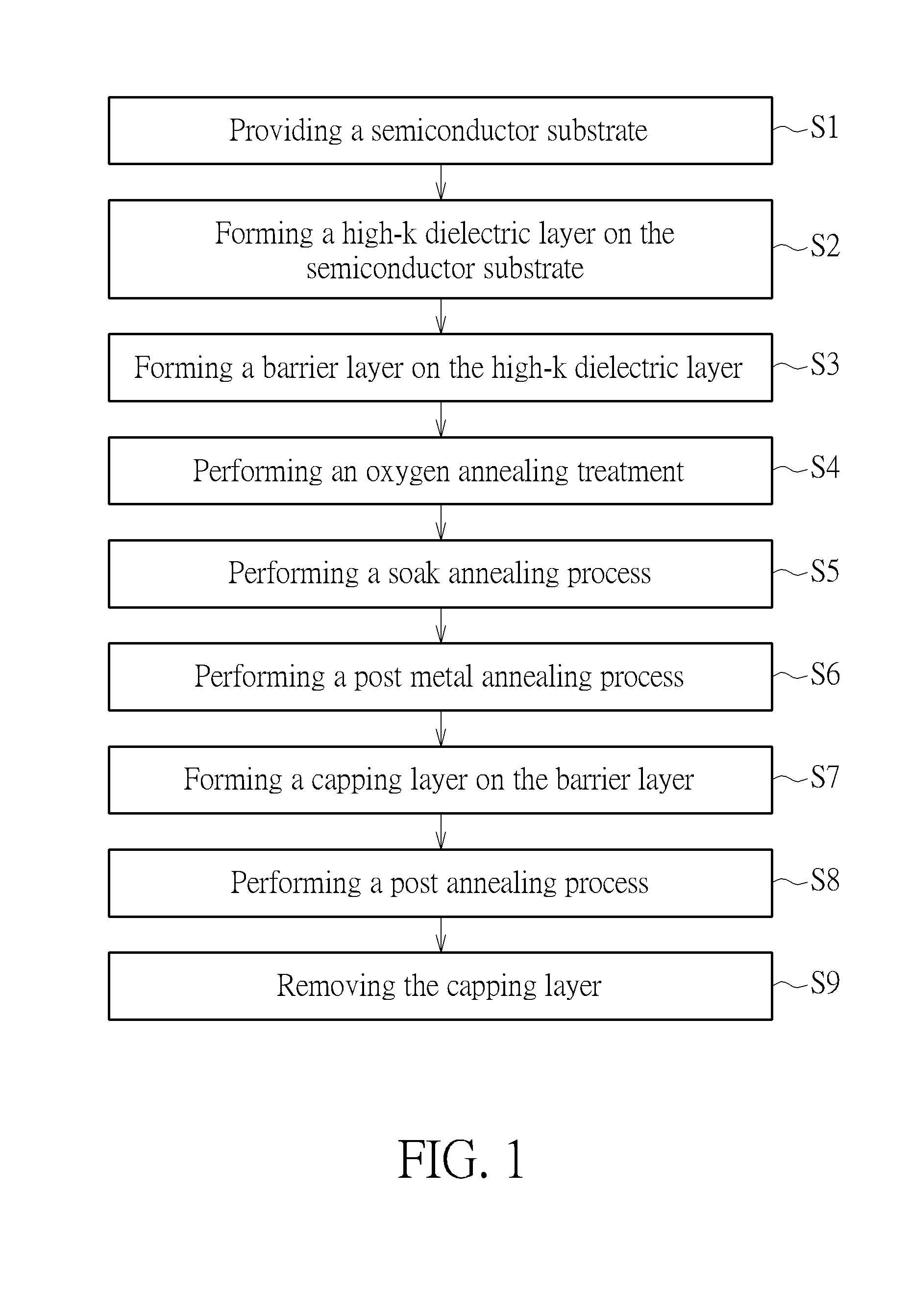
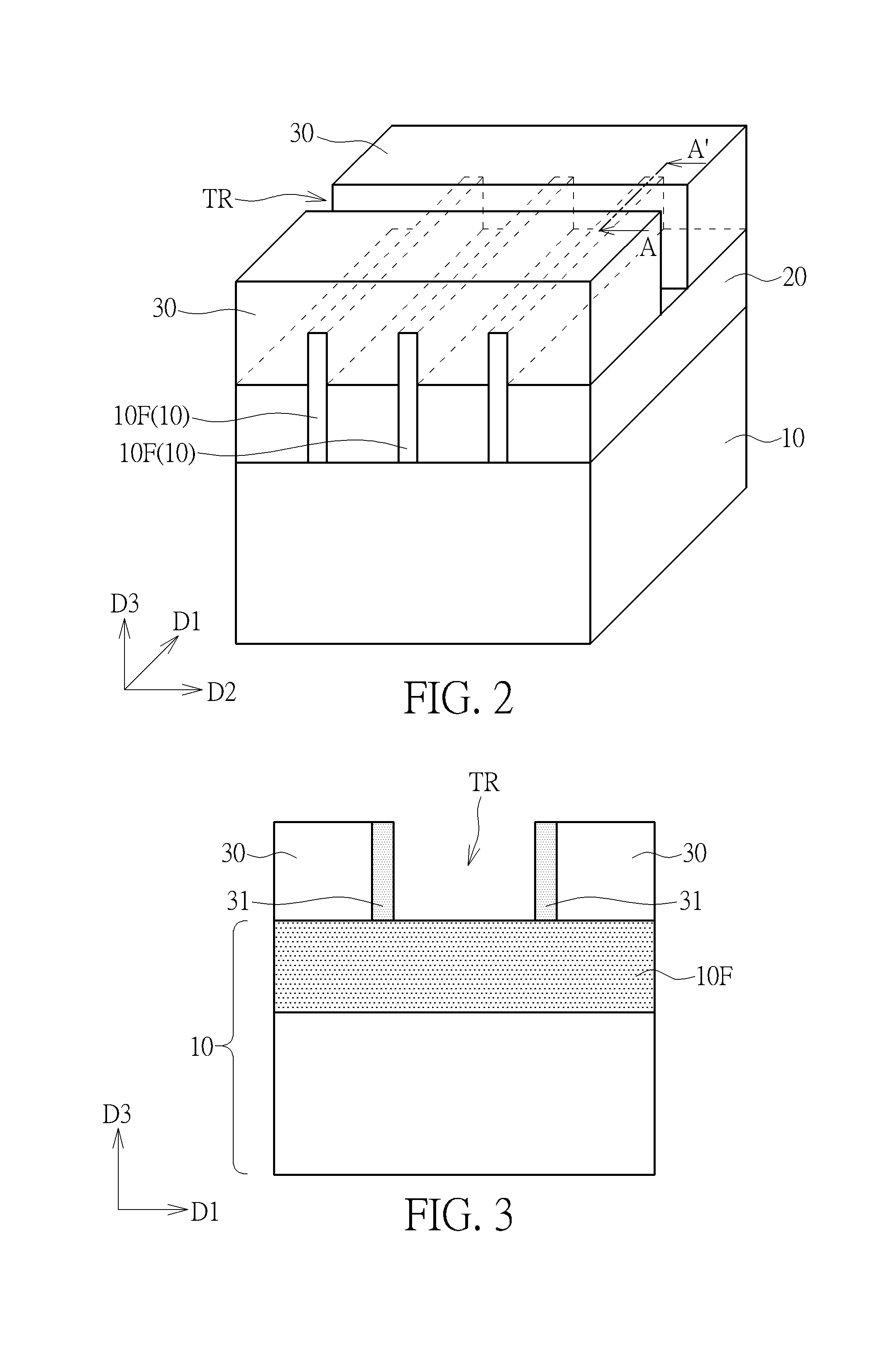
[0019]Please refer to FIGS. 1-8. FIG. 1 is a flow chart of a manufacturing method of a semiconductor structure according to a first embodiment of the present invention. FIGS. 2-8 are schematic drawings illustrating the manufacturing method of the semiconductor structure in this embodiment. As shown in FIGS. 1-3, in step S1, a semiconductor substrate 10 is provided. The semiconductor substrate 10 may include a silicon substrate, an epitaxial silicon substrate, a silicon germanium substrate, a silicon carbide substrate, or a silicon-on-insulator (SOI) substrate, but not limited thereto. In this embodiment, the semiconductor substrate 100 may include a plurality of fins 10F protruding in a vertical direction D3 and extending in a first direction D1, and a shallow trench isolation (STI) 20 may be formed between the fins 10F, but not limited thereto. Additionally, in the manufacturing method of this embodiment, for a replacement metal gate (RMG) process, an interlayer dielectric (ILD) 30...


PUM

PropertyMeasurementUnit
temperatureaaaaaaaaaa

Abstract

A manufacturing method of a semiconductor structure includes the following steps. A high-k dielectric layer is formed on a semiconductor substrate, and a barrier layer is formed on the high-k dielectric layer. An oxygen annealing treatment is performed after the step of forming the barrier layer; and a capping layer is formed on the barrier layer after the oxygen annealing treatment.

Description

BACKGROUND OF THE INVENTION[0001]1. Field of the Invention[0002]The present invention relates to a manufacturing method of a semiconductor structure, and more particularly, to a manufacturing method of a semiconductor structure with an oxygen annealing treatment on a barrier layer.[0003]2. Description of the Prior Art[0004]In the continuously improved semiconductor integrated circuit technology, the sizes of the semiconductor devices become smaller for increasing the integrity of the integrated circuit. In the scaling down process, the thickness control of layers in the semiconductor device becomes more and more critical. For improving the metal-oxide-semiconductor field effect transistor (MOSFET) device performance as feature sizes continue to decrease, the traditional gate oxide and polysilicon gate electrode are replaced by a high dielectric constant (high-k) gate dielectric and a metal gate electrode. In high-k gate stacks, the interfacial layer (IL) underlying the high-k dielec...

Claims


Application Information

Patent Timeline
Patent Type & Authority Patents(United States)
IPC IPC(8): H01L29/66H01L21/324H01L21/02H01L29/06H01L21/31H01L21/00
CPCH01L29/66795H01L21/02107H01L21/31H01L21/324H01L29/0653
Inventor HSIAO, YU-TUNGLIN, KENG-JENWANG, YU-REN
Owner UNITED MICROELECTRONICS CORP
Learn More