Negative-working lithographic printing plate precursor and use

a lithographic printing plate and precursor technology, applied in lithography, photomechanical equipment, instruments, etc., can solve the problems of increasing the number of printing sheets before such sheets become sellable, printing failures, undesirable presence of oxygen barrier layers, etc., to improve printing durability, fast imaging speed, and fast on-press development

Active Publication Date: 2016-06-14
EASTMAN KODAK CO
View PDF8 Cites 43 Cited by
  • Summary
  • Abstract
  • Description
  • Claims
  • Application Information

AI Technical Summary

Benefits of technology

[0029]The negative-working, infrared radiation-sensitive lithographic printing plate precursors of the present invention are capable of providing lithographic printing plates having significantly improved printing durability while maintaining other essential properties such as fast imaging speed, fast on-press development, minimal contamination to the fountain solution, and good thermal stability during storage of the precursors.

Problems solved by technology

For on-press development applications, the presence of an oxygen barrier layer is undesirable as it inhibits printing inks from attaching to the imageable layer in the laser exposed area and increases the number of printing sheets before such sheets become sellable.
Accumulation of such materials change the composition of fountain solutions and may break the ink-water balance during normal printing operation, leading to printing failures such as image “blinding” (inks failing to attached to the imaged areas) or “scumming” (inks attached to the non-printing surface of the printing plate), or both.
One of the disadvantages of using such advanced initiator compositions such as iodonium-borate compositions is that such compositions tend to crystallize on the surface of the imageable layer, a phenomenon common known as “blooming” in the art.
Blooming is particularly severe when particulate primary binders are used, as the initiator composition can only be located between the primary binder particles and have higher local concentration than in situations where the primary binders are in non-particulate form.
However, low average dry thickness often leads to low printing durability.
As a result, on-press developable printing plate precursors have been limited to short to medium run length printing applications.

Method used


Image

  • Negative-working lithographic printing plate precursor and use
  • Negative-working lithographic printing plate precursor and use
  • Negative-working lithographic printing plate precursor and use

Examples


invention example 1

[0158]To prepare negative-working lithographic printing plate precursors, a substrate with a hydrophilic surface was prepared in the following manner. The surface of an aluminum sheet was subjected to an electrolytic roughening treatment using hydrochloric acid to provide an average roughness (Ra) of 0.5 μm. The, the roughened aluminum sheet was anodized using an aqueous phosphoric acid solution to form an aluminum oxide layer of 2.5 g / m2. The aluminum sheet was then post-treated using a poly(acrylic acid) solution.

[0159]The infrared radiation-sensitive imageable layers were prepared using Formulation 1 shown in TABLE I below, which was applied onto the prepared aluminum substrate to provide a dry coverage of 1.5 g / m2 using a bar coater, followed by drying at 110° C. for 40 seconds and further cooling to 35° C. Thus, a negative-working infrared radiation-sensitive lithographic printing plate precursor was obtained.

[0160]

TABLE IComponentsAmountParticulate primary polymeric binder emu...

invention examples 2 to 15

[0162]These inventive examples were prepared as described in Invention Example 1 except that the particulate secondary resins that are shown below in TABLE II were used in place of Techpolymer SSX-105 in the infrared radiation-sensitive imageable layer and the coating weights were changed as shown in TABLE II.

[0163]

TABLE IIParticulate Secondary ResinAverageCoatingInventionParticle D2weightExampleBrand name(μm)(g / m2)2Techpolymer SSX-1055.01.03Techpolymer SSX-1055.02.04Techpolymer SSX-10888.01.55Techpolymer SSX-110910.01.56Techpolymer SSX-110910.02.57Techpolymer S SX-110910.03.58CHEMISNOW ® MX-300103.01.59CHEMISNOW ® MX-500115.01.510CHEMISNOW ® MR-7GC126.01.511TOSPEARL ® 2000B136.01.512Ganzpearl GS-0605146.51.513MIPELON ™ PM-2001510.01.514KTL-8FH163.51.515Art-pearl C-800176.01.58, 9Techpolymer SSX-108, SSX-110: Crosslinked acrylic beads (Sekisui Plastics Co., Ltd.).10-12CHEMISNOW ® MX-300, MX-500, MR-7GC: Crosslinked acrylic beads (Soken Chemical & Engineering Co., Ltd.).13TOSPEARL ® ...

invention example 16

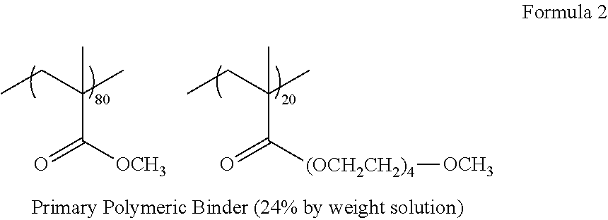
[0164]Another negative-working infrared radiation-sensitive lithographic printing plate precursor was prepared according to the present invention in the same manner as described in Invention Example 1, except that the polymeric emulsion18 was used as the primary polymeric binder in place of the primary polymeric binder shown in TABLE I. 18Copolymer derived from PEGMA1 / acrylonitrile / styrene (24% by weight solution, average particle size D1 of 150 nm).


PUM

PropertyMeasurementUnit
particle sizeaaaaaaaaaa

Abstract

A negative-working, infrared radiation-sensitive lithographic printing plate precursor is exposed and processed on-press to provide a lithographic printing plate. This precursor has an infrared radiation-sensitive imageable layer comprises free radical imaging chemistry; an infrared radiation absorber; a particulate primary polymeric binder comprising polyalkylene oxide segments having an average particle size (D1) of at least 50 nm and up to and including 1000 nm; and a particulate secondary resin having an average particle size (D2) of at least 3 μm and up to and including 10 μm. The imageable layer has an average dry thickness (t) of at least 1 μm and up to and including 4 μm and satisfies Equation (1):D2 / 1.4>t>D1   (1)and the average dry thickness (t) is defined by Equation (2):t=w / r   (2)wherein w is the dry coverage of the imageable layer in g / m2 and r is 1 g / cm3.

Description

RELATED APPLICATION[0001]Reference is made to U.S. Ser. No. 14 / 642,863 filed on Mar. 10, 2015, by Savariar-Hauck, Bruemmer, and Heinrich and entitled “Infrared Radiation-Sensitive Lithographic Printing Plate Precursors,” the disclosure of which is incorporated herein by reference.FIELD OF THE INVENTION[0002]This invention relates to negative-working, infrared radiation-sensitive lithographic printing plate precursors that can be imaged using suitable infrared radiation and then processed on-press. This invention also relates to methods for preparing lithographic printing plates from such precursors.BACKGROUND OF THE INVENTION[0003]In lithographic printing, lithographic ink receptive regions, known as image areas, are generated on a hydrophilic surface. When the hydrophilic surface is moistened with water and lithographic ink is applied, the hydrophilic regions retain the water and repel the lithographic ink and the lithographic ink receptive regions accept the lithographic ink and r...

Claims


Application Information

Patent Timeline
Patent Type & Authority Patents(United States)
IPC IPC(8): G03F7/00G03F7/038G03F7/20
CPCG03F7/0388G03F7/20G03F7/032B41C2210/04B41C2210/08B41C2210/24B41C2210/26B41C1/1008
Inventor KAMIYA, MASAMICHIHAYASHI, KOJISHEKIGUCHI, YOSHIAKIHAYAKAWA, EIJI
Owner EASTMAN KODAK CO
Why Eureka
Try Eureka