Wire electric discharge machining method and wire electric discharge machine for machining tool that uses ultra-hard material and is mounted to rotating shaft

a wire electric discharge machine and machining tool technology, applied in the direction of process control, process and machine control, instruments, etc., can solve the problems of poor machining efficiency, difficult machining operation, and significant wear of grindstones, and achieve high precision

Active Publication Date: 2016-07-05
FANUC LTD
View PDF43 Cites 7 Cited by
  • Summary
  • Abstract
  • Description
  • Claims
  • Application Information

AI Technical Summary

Benefits of technology

[0020]In the light of the above-described problems of conventional art, it is an object of the present invention to provide a wire electric discharge machining method and wire electric discharge machine that allow reducing, as much as possible, measurement error of the position of a rake face, and easing, as much as possible, the work burden of an operator involved in measurement, and that enable machining, easily and with high precision, of a cutting tool to which there is fixed an ultra-hard material, such as a polycrystalline diamond (PCD) material or polycrystalline cubic boron nitride (PCBN) material that is fixed to a rotating shaft.
[0028]The present invention succeeds thus in providing a wire electric discharge machining method and wire electric discharge machine that allow reducing, as much as possible, measurement error of the position of a rake face, and easing, as much as possible, the work burden of an operator involved in measurement, and that enable machining, easily and with high precision, of a cutting tool to which there is fixed an ultra-hard material, such as a polycrystalline diamond (PCD) material or polycrystalline cubic boron nitride (PCBN) material that is fixed to a rotating shaft.

Problems solved by technology

In high-precision machining of a cutting edge of a rotary-type cutting tool to which there is mounted, in the form of a cutting edge, a polycrystalline diamond (PCD) material or polycrystalline cubic boron nitride (PCBN) material, which are the hardest cutting tool materials, the materials themselves are extremely hard, and hence the machining operation is difficult.
Moreover, grindstone wear is significant, and machining efficiency poor, in the case of fine shapes or complex and intricate machining shapes.
However, an expensive disc electrode must be prepared every time, in accordance with the PCD tool shape, and the entire shape must be burned through discharge.
The machining time of deep-groove shapes or the like is thus extremely long.
Also, a plurality of disc electrodes are required, on account of disc electrode consumption, which is a further factor that drives up the machining unit cost of the tool.
The operation involved, however, is not easy.
If the position of the rake face is not measured accurately, a machining error ensues as a matter of course.
This machining error becomes manifest mainly in the form of a rotation radius precision error of the cutting tool, upon rotation of the tool.
In the case of cutting tools having complex outer peripheral shapes, in particular circular arc shapes, however, instances arise in which mere correction in the radial direction by circular arc quadrants is inadequate.
In the case of elongated blade shapes, an elongated PCD tip becomes often brazed curvedly, on account of heat during brazing of the PCD tip, so that high tool radius precision cannot be achieved unless this curved portion is measured (FIG. 27).
Needless to say, the degree of curving of a long PCD tip that is brazed cannot be worked out accurately even in the case of a linear shape, as in the technology disclosed in Japanese Patent Application Publication No. 11-267925 (FIG. 28), as a result, the associated error translates into a tool radius error, thereby making it difficult to produce a tool with high precision.
However, no correction means are provided herein, let alone for a machining shape of a cutting blade having a circular arc shape.
It is also evident that a rotating tool having a spiral cutting blade, such as the one illustrated in FIG. 28, is difficult to machine, with high precision, in the above machining methods.

Method used


Image

  • Wire electric discharge machining method and wire electric discharge machine for machining tool that uses ultra-hard material and is mounted to rotating shaft
  • Wire electric discharge machining method and wire electric discharge machine for machining tool that uses ultra-hard material and is mounted to rotating shaft
  • Wire electric discharge machining method and wire electric discharge machine for machining tool that uses ultra-hard material and is mounted to rotating shaft

Examples


Embodiment Construction

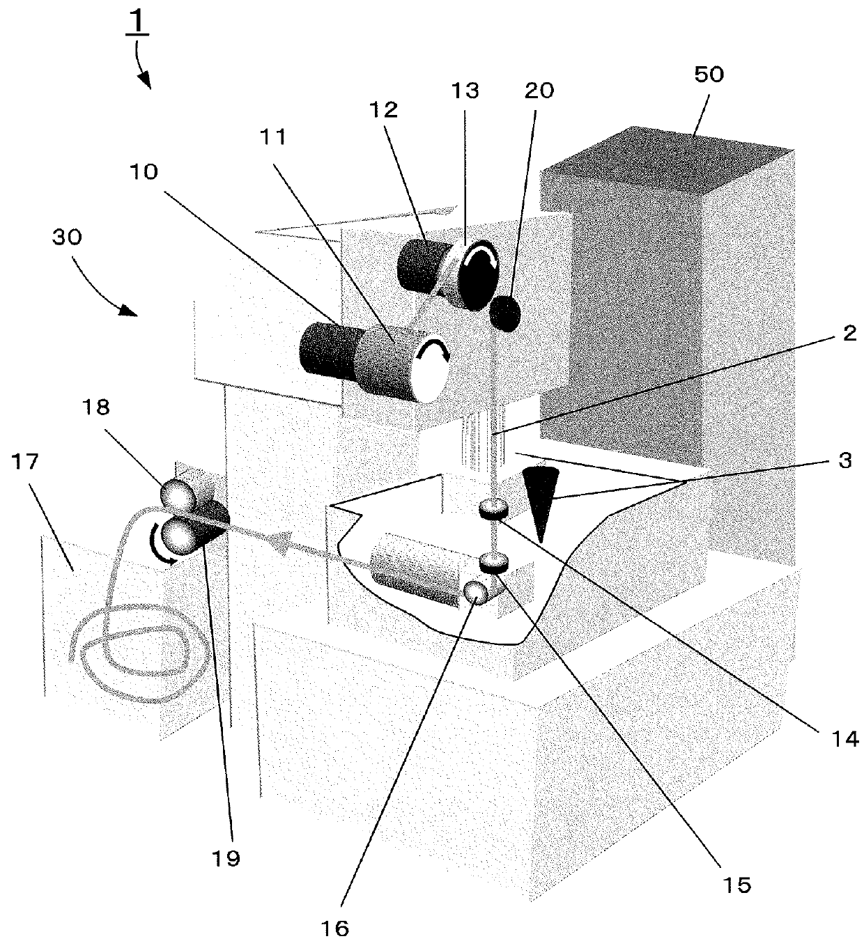
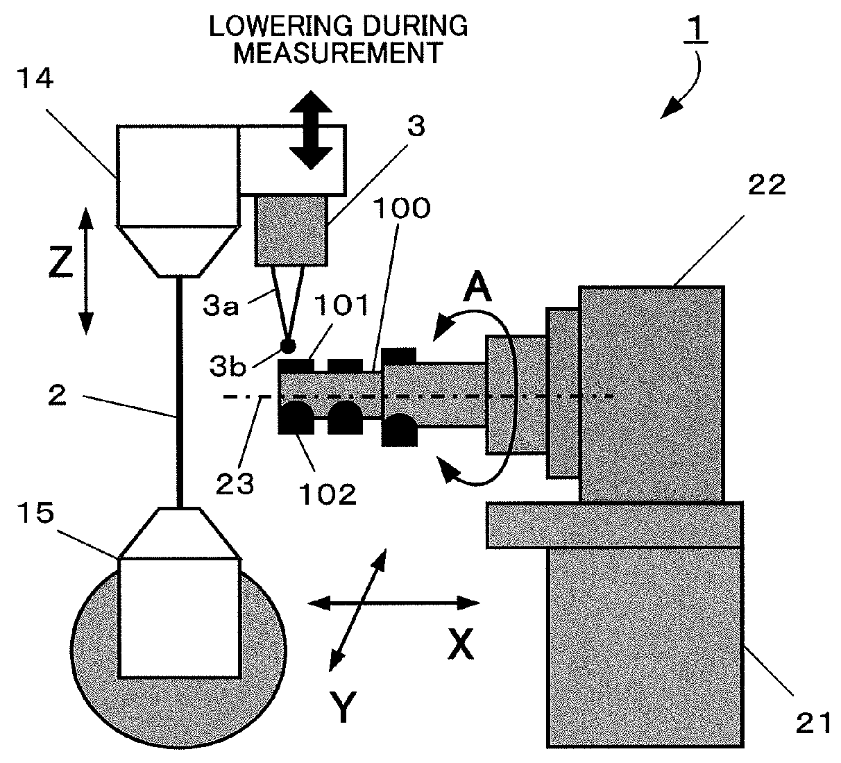
[0059]FIG. 1 is a schematic diagram for explaining a wire electric discharge machine according to the present invention. FIG. 2 is a schematic diagram for explaining a wire electric discharge machine, according to the present invention, having a rotating shaft that causes a workpiece to rotate.

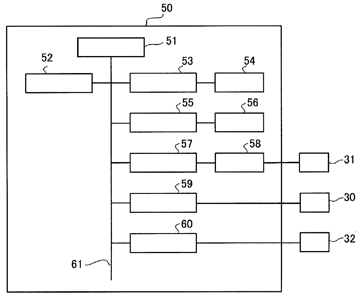
[0060]A wire electric discharge machine 1 comprises a wire electric discharge machine main body 30 and a controller 50 that controls the wire electric discharge machine main body 30. A wire bobbin 11 around which a wire electrode 2 is wound is imparted with an instructed predetermined low torque, in an opposite direction to a draw-out direction of the wire electrode 2, by a feed-out section torque motor 10. The wire electrode 2 that is paid out of the wire bobbin 11 passes along a plurality of guide rollers (not shown), and the tension of the wire electrode 2 is adjusted, by a brake shoe 13 that is driven by a brake motor 12, between the brake shoe 13 and a feed roller 19 that is driven by a w...


PUM

PropertyMeasurementUnit
radiusaaaaaaaaaa
radiusaaaaaaaaaa
radiusaaaaaaaaaa

Abstract

An ultra-hard material fixed to a cutting tool is formed into a cutting blade by electric discharge machining. The wire electric discharge machine has a rotating shaft to which the cutting tool is mounted, and has a touch sensor mounted to an upper wire guide. A measurement program is generated on the basis of a machining path instructed by the machining program. A machining program is regenerated from rotating shaft coordinate information and path coordinate position information obtained at measurement points, on the basis of the measurement program. As a result, a rake face position of the cutting tool can be accurately measured and a wire electrode can be positioned accurately with respect to that position during machining.

Description

RELATED APPLICATIONS[0001]The present application claims priority from, Japanese Application Number 2011-259487, filed Nov. 28, 2011, the disclosure of which is hereby incorporated by reference herein in its entirety.BACKGROUND OF THE INVENTION[0002]1. Field of the Invention[0003]The present invention relates to a wire electric discharge machining method and a wire electric discharge machine for high-precision machining of a cutting edge of a rotary-type cutting tool that is mounted with, as a cutting edge, a polycrystalline diamond (PCD) material or polycrystalline cubic boron nitride (PCBN) material, which are the hardest cutting tool materials.[0004]2. Description of the Related Art[0005]Herein, a polycrystalline diamond (PCD) material or polycrystalline cubic boron nitride (PCBN) material, which are the hardest cutting tool materials, is cut out (blanking), in the form of tips, from PCD or PCBN stock, and a brazing material is fused in a high-frequency induction heater, to braze...

Claims


Application Information

Patent Timeline
Patent Type & Authority Patents(United States)
IPC IPC(8): B23H7/20B23H7/06G01B7/008B23H9/00B23H9/08B23H7/02
CPCB23H7/06B23H9/00B23H9/08G01B7/008B23H7/02B23H7/20G05B2219/37444G05B2219/37452
Inventor ARAKAWA, YASUOTAKAYAMA, YUSHI
Owner FANUC LTD
Why Eureka
Try Eureka