Control circuit for a DC motor

a control circuit and motor technology, applied in the direction of control systems, electronic commutation motor control, dc motor stoppers, etc., can solve the problems of damage to the control circuit of the fan, inability to cool or exhaust as expected,

Active Publication Date: 2016-07-05
JOHNSON ELECTRIC SA
View PDF25 Cites 241 Cited by
  • Summary
  • Abstract
  • Description
  • Claims
  • Application Information

AI Technical Summary

Benefits of technology

[0030]In the present invention, the shunt circuit, the blocking circuit or the both, regardless the direction of the BEMF generated by the DC motor, can inhibit the current produced by the BEMF, thus protecting the whole circuitry.

Problems solved by technology

However, there is a possibility that the fan doesn't rotate in the pre-determined direction in some abnormal situation.
For example, when a cooling fan, positioned at the front of a car, is facing against a strong wind during the car's running, or an exhaust fan for a kitchen is subjected to a strong wind from the outside to the inside, the fans may rotate in the reverse direction, resulting in an inability to cool or exhaust as expected.
This may damage the control circuit for the fan if the generated BEMF is too high.

Method used


Image

  • Control circuit for a DC motor
  • Control circuit for a DC motor
  • Control circuit for a DC motor

Examples


first embodiment

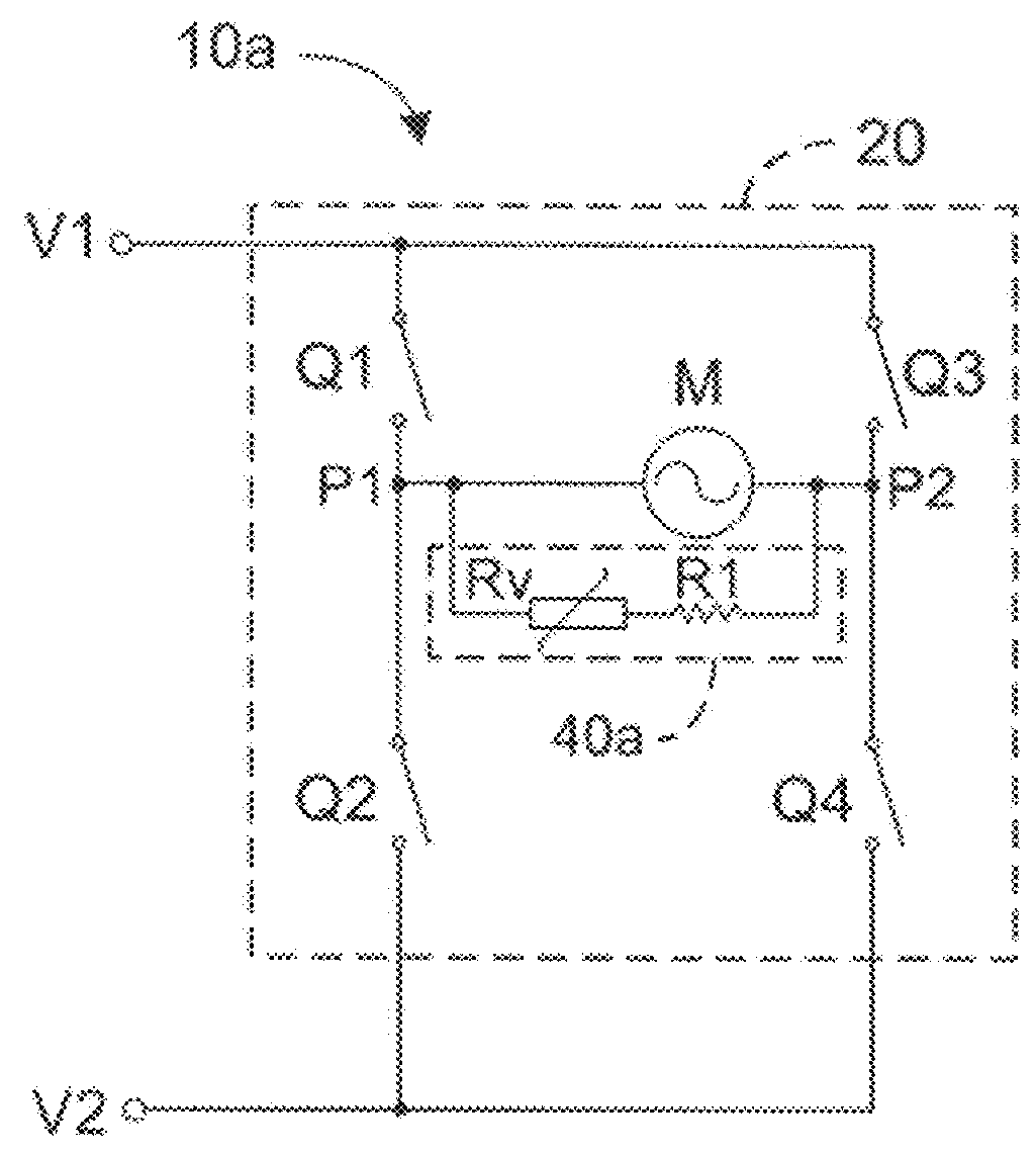
[0041]Referring to FIG. 1, a control circuit 10a for a DC motor according to the present invention, which is used to drive a DC motor M, comprises a first DC port V1, a second DC port V2, a H-bridge driving circuit 20 and a shunt circuit 40a.

[0042]The first and the second DC ports V1, V2 are used to connect to a DC source. H-bridge driving circuit 20 comprises a first switch Q1, a second switch Q2, a third switch Q3 and a fourth switch Q4, each of which has a control end applied for controlling its on-off. All the aforesaid switches can be BJT (Bipolar Junction Transistor), MOSFET (Metal Oxide Semiconductor Field Effect Transistor) or other kind of transistors, and every switch within itself defines a diode that, for example, is between its collector and emitter electrode if it is a BJT, or between its source and drain electrode if it is a MOSFET. It is pointed out that every switch in this or any other embodiment of the present invention may be represented simply by a graphic swit...

third embodiment

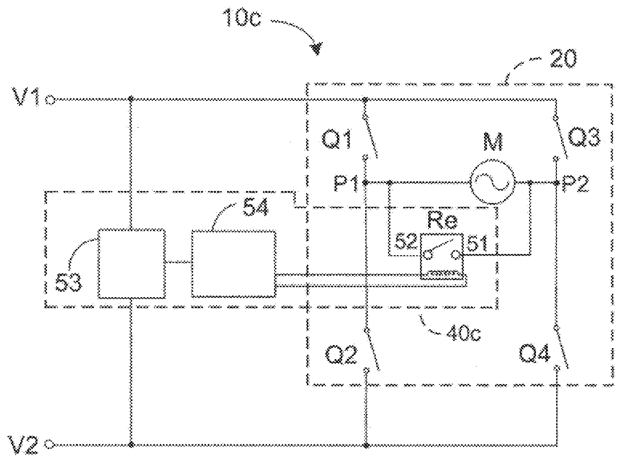
[0055]Referring to FIG. 3, a control circuit 10c for a DC motor is different from the control circuit 10a in that the aforesaid varistor Rv included in the shunt circuit 40a is substituted by a relay Re. Specifically, the shunt circuit 40c includes: a relay Re with a first contact 51 connected to the second output port P2 and with a second contact 52 connected to the first output port P1; a voltage detecting circuit 53 for detecting the voltage between the first and the second DC ports V1, V2; and a controller 54, connected between the voltage detecting circuit 53 and the relay Re, for controlling the relay Re to close when a voltage higher than a predetermined value is detected by the voltage detecting circuit 53. Optionally, the voltage detecting circuit 53 and the relay Re are integrated into a control unit.

[0056]Thus, when the DC motor is forced to rotate by an external force so as to generate a BEMF, the voltage between the first and the second DC ports V1, V2 will change, and...

sixth embodiment

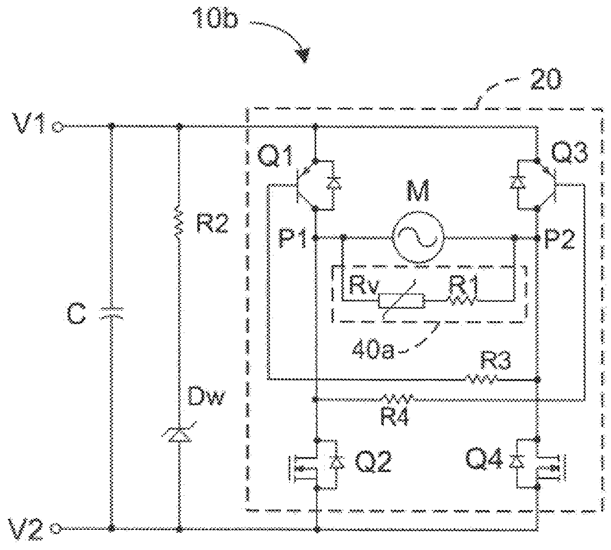
[0067]Optionally, add a second resistor R2, a zener diode Dw, a third resistor R3 and a fourth resistor R4, even a capacitor C in this embodiment, all as same as that according to the second or the sixth embodiment, the ways of connection and the function of which are as aforesaid, which won't be reiterated.

[0068]In the description and claims of the present application, each of the verbs “comprise”, “include”, “contain” and “have”, and variations thereof, are used in an inclusive sense, to specify the presence of the stated item or feature but do not preclude the presence of additional items or features.

[0069]It is appreciated that certain features of the invention, which are, for clarity, described in the context of separate embodiments, may also be provided in combination in a single embodiment. Conversely, various features of the invention which are, for brevity, described in the context of a single embodiment, may also be provided separately or in any suitable sub-combination.


PUM


Abstract

A control circuit for a DC motor, has: a first and second input ports for connection to a DC source; a H-bridge driving circuit, having first and second switches connected in series between the input ports, and third and fourth switches connected in series between the input ports, a first output port between the first and second switches and a second output port between the third and fourth switches, and a shunt circuit and / or a blocking circuit. The motor is connected between the first and second output ports. The shunt circuit is connected between the first second output ports and has a resistance that will decrease in response to BEMF generated by the motor. The blocking circuit is connected in series with the motor between the output ports and has a resistance that increases in response to BEMF generated by the motor.

Description

CROSS REFERENCE TO RELATED APPLICATIONS[0001]This non-provisional patent application claims priority under 35 U.S.C. §119(a) from Patent Application No. 201310616819.6 filed in The People's Republic of China on 27 Nov. 2013.FIELD OF THE INVENTION[0002]This invention relates to a control circuit for a DC (Direct Current) motor, and in particular, to a control circuit with a protection function for a DC motor.BACKGROUND OF THE INVENTION[0003]A cooling or exhaust fan, which has a DC motor, is usually designed to rotate in only one direction. However, there is a possibility that the fan doesn't rotate in the pre-determined direction in some abnormal situation. For example, when a cooling fan, positioned at the front of a car, is facing against a strong wind during the car's running, or an exhaust fan for a kitchen is subjected to a strong wind from the outside to the inside, the fans may rotate in the reverse direction, resulting in an inability to cool or exhaust as expected.[0004]One ...

Claims


Application Information

Patent Timeline
Patent Type & Authority Patents(United States)
IPC IPC(8): H02P6/18H02P3/12H02P6/00H02P7/285H02P7/29H02P7/291
CPCH02P6/06H02P3/12H02P7/285
Inventor SUN, CHI PINGXIN, FEIYANG, XIU WENYEUNG, SHING HINJIANG, YUN LONGCUI, YAN YUNWONG, SIN SANGYI, ZHU QING
Owner JOHNSON ELECTRIC SA
Why Eureka
Try Eureka