Apparatus for manufacturing an inorganic thin-film solar cell, and method for controlling same

a technology of solar cells and inorganic thin films, which is applied in the direction of sustainable manufacturing/processing, final product manufacturing, coatings, etc., can solve the problems of limited high cost and time-consuming process of solar cell layer formation, etc., to reduce material cost, improve solar cell efficiency, and reduce manufacturing cost

Active Publication Date: 2016-07-26
KOREA UNIV RES & BUSINESS FOUND
View PDF14 Cites 2 Cited by
  • Summary
  • Abstract
  • Description
  • Claims
  • Application Information

AI Technical Summary

Benefits of technology

[0028]According to the apparatus for manufacturing an inorganic thin-film solar cell and a method for controlling the same of the present invention having the same configuration as described above have the following advantageous effects.
[0029]First, according to the apparatus for manufacturing an inorganic thin-film solar cell and a method for controlling the same of the present invention, although an expensive fine nozzle is not implemented through a low-temperature spray scheme, the discharge of the inorganic powder aerosol having fine particles is possible, and the micro solar cell layer can be formed in an accurate and stable manner through the voltage supply unit, thereby improving the efficiency of the solar cell and reducing the manufacturing cost.
[0030]Second, according to the apparatus for manufacturing an inorganic thin-film solar cell and a method for controlling the same of the present invention, the necessity of an expensive fine nozzle is eliminated through a low-temperature spray scheme so that a powder aerosol containing the inorganic powder having micro-sized particles can be discharged, thereby significantly reducing the material cost and thus the manufacturing cost.
[0031]Third, according to the apparatus for manufacturing an inorganic thin-film solar cell and a method for controlling the same of the present invention, a simple non-contact formation of the solar cell layer is possible, making it possible to form the micro solar cell layer more accurately, thereby remarkably increasing the production yield owing to simplification of the manufacturing process.
[0032]Fourth, according to the apparatus for manufacturing an inorganic thin-film solar cell and a method for controlling the same of the present invention, the simultaneous spray or selective local spray is possible through the multi-nozzle to accurately adjust compactness of a structure (texture) of the solar cell layer such as a CIGS layer so that a solar cell layer having excellent durability can be formed.
[0033]Fifth, according to the apparatus for manufacturing an inorganic thin-film solar cell and a method for controlling the same of the present invention, the simultaneous spray or selective local spray is possible through the multi-nozzle to accurately and uniformly adjust the composition ratio of a structure of the solar cell layer such as a CIGS layer so that a high efficiency solar cell layer having excellent uniformity can be formed.

Problems solved by technology

A conventional solar cell solar cell layer formation method mostly employs an expensive and time-consuming process such as sputtering, thermal evaporation, CVD, and PVD.
However, such conventional screen printing and ink-jet printing techniques has a disadvantage in that the solar cell layer formation is limited due to the contact problem of the screen printing technique and the discharge limitation of the ink-jet printing technique.
However, as shown in FIG. 2, the conventional screen printing technique entails a problem in that in a spreading area As of the left and right sides of the center having the maximum height h1, the layer 6b formed one side of the substrate 1 has a height lower than the maximum height h1, and thus the aspect ratio is considerably low, leading to a reduction in the light-receiving area of a solar cell and thus an increase in the shading loss, thereby deteriorating the efficiency of the solar cell.
Such conventional various methods involve a problem in that a large area is difficult to implement, contamination is serious inside a vacuum device, and a thin film having a good quality is not easy to manufacture.
However, there occurs a problem in that since a carbon layer is present as a residue in the thus produced CIGS thin film, it significantly degrades the optical conversion efficiency.

Method used


Image

  • Apparatus for manufacturing an inorganic thin-film solar cell, and method for controlling same
  • Apparatus for manufacturing an inorganic thin-film solar cell, and method for controlling same
  • Apparatus for manufacturing an inorganic thin-film solar cell, and method for controlling same

Examples


Embodiment Construction

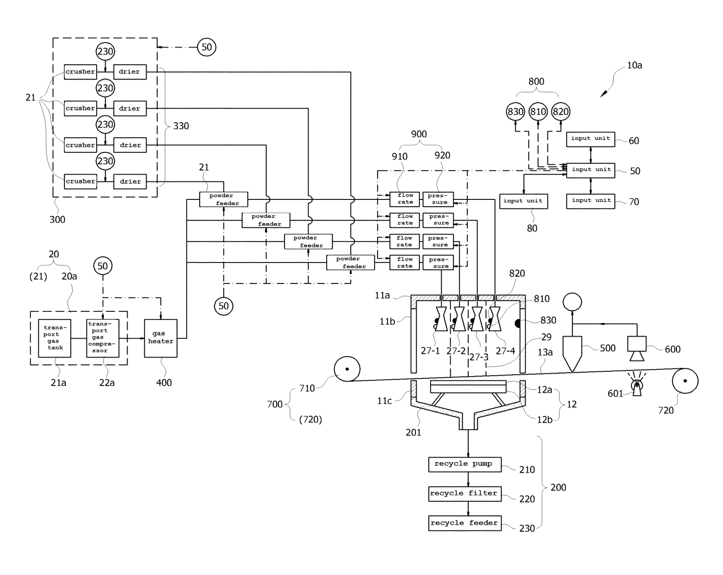
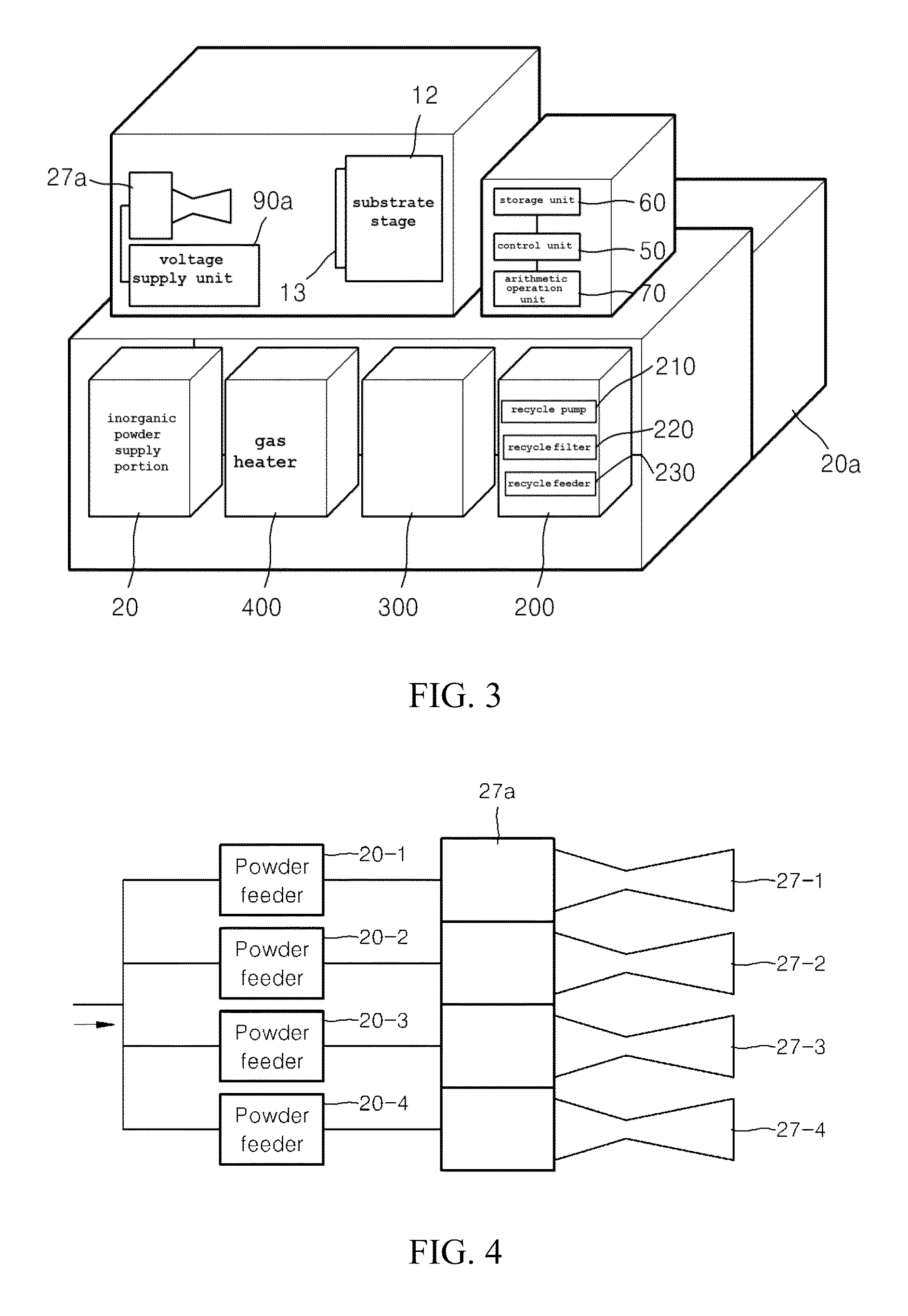
[0053]Now, preferred embodiments of an apparatus for manufacturing an inorganic thin-film solar cell and a method for controlling the same according to the present invention will be described hereinafter in detail with reference to the accompanying drawings.

[0054]FIG. 3 is a schematic state view illustrating an apparatus for manufacturing an inorganic thin-film solar cell according to an embodiment of the present invention, FIG. 4 is a state view illustrating an example of a multi-nozzle of an apparatus for manufacturing an inorganic thin-film solar cell according to an embodiment of the present invention, FIG. 5 is a state view illustrating another example of a multi-nozzle of an apparatus for manufacturing an inorganic thin-film solar cell according to an embodiment of the present invention, and FIG. 6 is a state view illustrating still another example of a multi-nozzle of an apparatus for manufacturing an inorganic thin-film solar cell according to an embodiment of the present in...


PUM

PropertyMeasurementUnit
thicknessaaaaaaaaaa
pressureaaaaaaaaaa
flow rateaaaaaaaaaa

Abstract

The present invention relates to an apparatus for manufacturing an inorganic thin-film solar cell, the apparatus including: a substrate stage which is mounted in a chamber and in which a solar cell substrate is disposed; and an inorganic powder supply unit including a nozzle configured to discharge an inorganic powder aerosol containing an inorganic powder onto the substrate stage in a supersonic flow so as to form a solar cell layer on the solar cell substrate, and an inorganic powder supply portion configured to supply the inorganic powder aerosol to the nozzle.

Description

TECHNICAL FIELD[0001]The present invention relates to an apparatus for manufacturing a solar cell, and more particularly, to an apparatus for manufacturing a solar cell, in which the solar cell having a fine and dense structure can be manufactured.BACKGROUND ART[0002]A conventional solar cell solar cell layer formation method mostly employs an expensive and time-consuming process such as sputtering, thermal evaporation, CVD, and PVD.[0003]As an alternative method to the conventional method, techniques such as screen printing and ink-jet printing have been proposed. However, such conventional screen printing and ink-jet printing techniques has a disadvantage in that the solar cell layer formation is limited due to the contact problem of the screen printing technique and the discharge limitation of the ink-jet printing technique.[0004]In other words, in FIGS. 1(a) and 1(b), there is shown a conventional electrode forming process employing the screen printing technique according to the...

Claims


Application Information

Patent Timeline
Patent Type & Authority Patents(United States)
IPC IPC(8): H01L31/18C23C24/04H01L31/20H01L31/0749H01L31/032H01L21/02
CPCH01L31/18C23C24/045H01L31/0322H01L31/0749H01L31/206H01L21/0259H01L21/02568H01L21/02628Y02E10/541Y02P70/521C23C24/04Y02P70/50
Inventor PARK, JUNG JAEKIM, DO YEONLEE, JONG GUNLEE, MIN WOOKYOON, SUK GOO
Owner KOREA UNIV RES & BUSINESS FOUND
Why Eureka
Try Eureka