
ZVS DC/DC converter for converting voltage between a battery and a DC link in a hybrid energy storage system and method thereof

a hybrid energy storage system and converter technology, applied in the direction of electric variable regulation, process and machine control, instruments, etc., can solve the problems of serious stresses on the switches in the converter, low switching efficiency, and low conversion efficiency, so as to improve control flexibility, reduce switching voltage, and reduce the effect of inductor current rippl

Active Publication Date: 2016-08-16
UNIV OF MARYLAND
View PDF4 Cites 26 Cited by
  • Summary
  • Abstract
  • Description
  • Claims
  • Application Information

AI Technical Summary

Benefits of technology

The present invention is a type of DC-to-DC converter that uses a split ultra-capacitor bank to provide flexibility in outputting a required voltage level. It can operate with three voltage levels, which allows for better flexibility in controlling the output and reduces the need for high-current inductors, resulting in lower current ripple and lower voltage ratings. The overall technical effects of this invention are increased flexibility and efficiency in DC-to-DC conversion.

Problems solved by technology

For example, the DC / DC boost converters may not meet the criteria of electrical isolation.
Moreover, the large variance in magnitude between the input and the output may impose serious stresses on the switches in the converter.
This topology also may suffer from high current and voltage ripples, and has a large volume and weight.
This structure, however, cannot operate efficiently when a high voltage step-up ratio is required since the duty cycle is limited by the circuit impedance leading to a maximum step-up ratio of approximately 4.
However, it causes some undesirable effects, such as, for example, the radio frequency interference ignition.
Another drawback of DC / DC converters is the operation with considerable energy losses including the losses produced by the semiconductor switches (IGBTs and diodes) and the passive components (capacitors and inductors).

Method used


Image

  • ZVS DC/DC converter for converting voltage between a battery and a DC link in a hybrid energy storage system and method thereof
  • ZVS DC/DC converter for converting voltage between a battery and a DC link in a hybrid energy storage system and method thereof
  • ZVS DC/DC converter for converting voltage between a battery and a DC link in a hybrid energy storage system and method thereof

Examples


Embodiment Construction

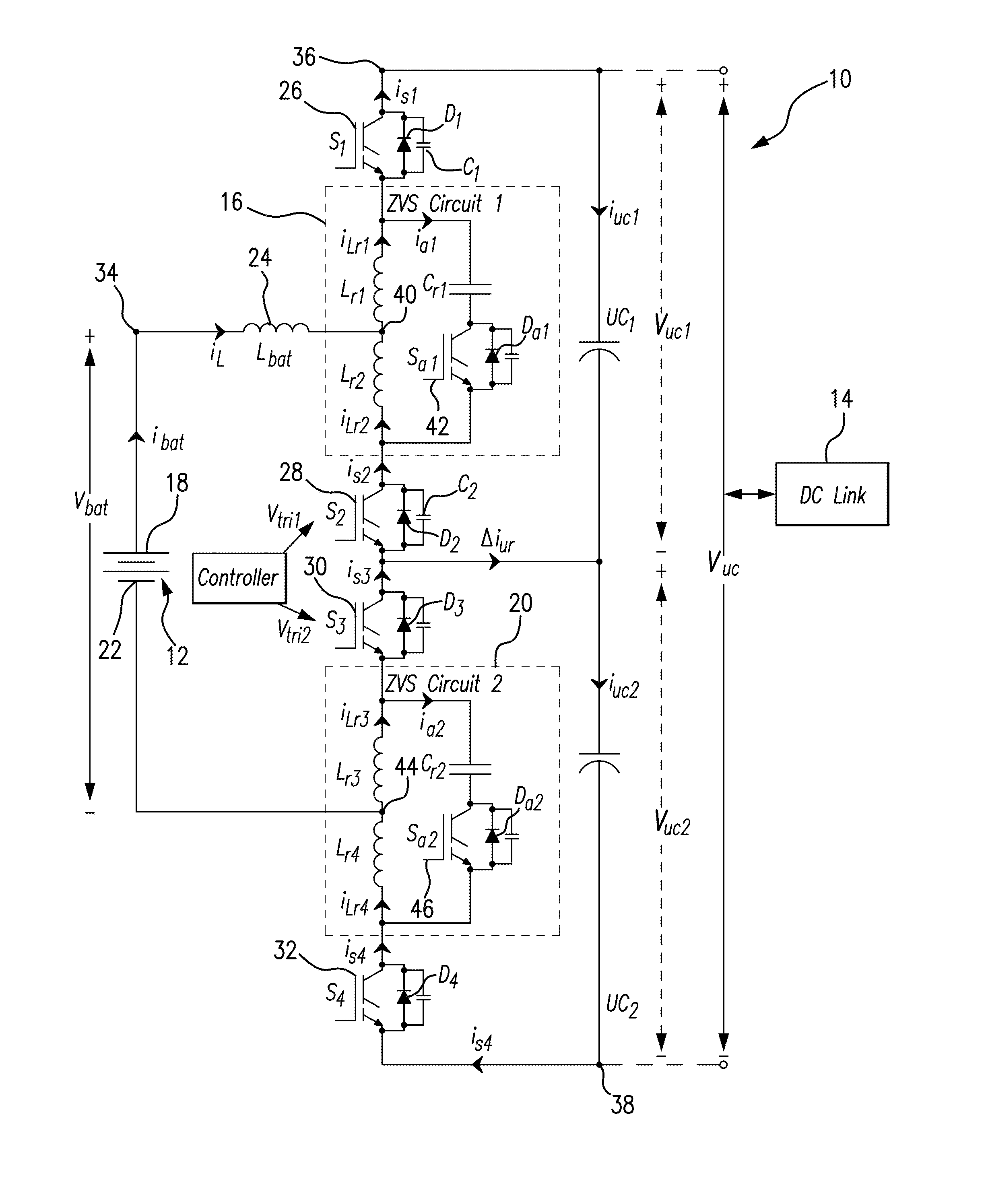
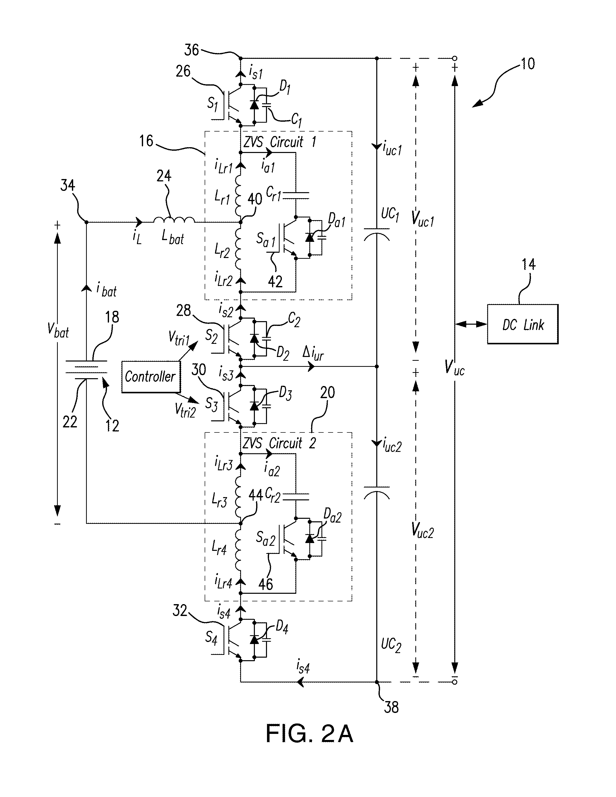
[0072]As shown in FIGS. 2A and 2B, the bi-directional ZVS (zero-voltage switching) DC / DC converter 10 is interconnected between a battery 12 and a DC link 14 in an Electric Vehicle drive system.

[0073]The DC / DC converter 10 includes a ZVS circuit 16 coupled to a terminal 18 of the battery 12, and a ZVS circuit 20 coupled to the terminal 22 of the battery 12. As shown in FIG. 1, the ZVS circuit 16 is coupled to the terminal 18 of the battery through a transfer inductor 24.

[0074]The DC / DC converter 10 further includes four main switches including switch S1, switch S2, switch S3, and switch S4. Switches S1-S4, are built with a solid state element, for example, respective Insulated-Gate Bipolar Transistors (IGBTs) 26, 28, 30 and 32, each of which has a respective intrinsic diode (D1, D2, D3, or D4,) which are body diodes of IGBTs.

[0075]The main switch S1 is connected to the node 34 (at the terminal 18 of the battery 12).

[0076]The main switches S2 and S3 are coupled in series between the ...


PUM


Abstract

The bi-directional DC / DC converter has zero voltage switching (ZVS) soft switching capability resulting in a higher efficiency, and provides reduction of the switching losses due to higher switching frequencies. The capability of operation in higher frequencies results in reducing the size of passive components including inductance and capacitors. The subject DC / DC converter is capable of operating with three voltage levels in both power flow directions, thus providing flexibility in the voltage control and attaining lower inductor current ripple and lower switch voltage ratings. DC link capacitors are replaced with ultra capacitor banks split in two.

Description

REFERENCE TO RELATED APPLICATIONS[0001]This Utility Patent Application is based on a Provisional Patent Application No. 61 / 764,325 filed 13 Feb. 2013.FIELD OF THE INVENTION[0002]The present invention is directed to hybrid energy storage systems; and more in particular, to DC / DC converters serving as an interface between a battery and the DC drive link in Hybrid Energy Storage Systems.[0003]In overall concept, the present invention directs itself to a bi-directional DC / DC converter for Hybrid Energy Storage Systems which has a high efficiency due to Zero-Voltage Switching (ZVS) soft switching in both power flow directions, and negligent inductor ripples.[0004]The present invention also is directed to a Hybrid Energy Storage System using a DC / DC converter which is designed with a split ultracapacitor bank permitting elimination of the DC link capacitors.[0005]Additionally, the present invention is directed to a DC / DC converter for a Hybrid Energy Storage System which provides an enhan...

Claims


Application Information

Patent Timeline
IPC IPC(8): H02M3/158H02M1/14
CPCH02M3/158H02M1/14H02M3/1582Y02B70/10H02M1/0058
Inventor KHALIGH, ALIREZADUSMEZ, SERKAN
Owner UNIV OF MARYLAND
Learn More