Bone cement mixing and delivery system and methods of use thereof

a technology of bone cement and mixing device, which is applied in the direction of osteosynthesis device, transportation and packaging, prosthesis, etc., can solve the problems of difficult to achieve uniformity, messy and time-consuming transfer step, and open mixing and transfer step also present contamination risk, so as to reduce contamination risk and preparation time, improve cement injectability, and eliminate open mixing and transfer steps

Inactive Publication Date: 2016-08-30
ETEX
View PDF30 Cites 40 Cited by
  • Summary
  • Abstract
  • Description
  • Claims
  • Application Information

AI Technical Summary

Benefits of technology

[0004]The present invention features an enclosed bone cement mixing and delivery system. The present mixing and delivery system is based on syringe-to-syringe mixing, which eliminates the open mixing and transfer steps and reduces contamination risk and preparation time. The system also improves cement injectability and includes a packaging design that promotes powder filling and extends shelf life.
[0009]In another embodiment, the powder is compressed to a desired density to enhance the wetting characteristics, optimize mixing forces, and minimize the amount of air in the mixed product. In a preferred embodiment, the powder has a density in the range of about 0.1 to about 1.2 g / cc, preferably, 0.5, 0.6, 0.7, 0.8, 0.9, 1.0, 1.1, or 1.2 g / cc, and most preferably 1.0 g / cc. In another embodiment; the tube with powder has an affixed porous cap to aid powder filling and compaction by venting air; the porous cap allows air to escape from the tube, but prevents escape of the powder. In preferred embodiments, the porous cap has pores that are less than or equal to 1.0 mm in diameter, preferably less than or equal to 750, 500, 300, 250, 150, and 100 μm in diameter, and more preferably less than 75, 50, 25, 15, 10, and 5 μm in diameter, and most preferably less than or equal to 1, 0.5, 0.4, 0.3, 0.2, 0.1, and 0.05 μm in diameter. The cap also allows released moisture to exit the device, which extends shelf life and long term stability of the powder during storage by preventing degradation of the powder components. In another embodiment, the cap is composed of a porous polymer, ceramic, or metal material.
[0011]The powder-containing tube and the liquid-containing tube can be joined end-to-end such that there is communication between the tubes that allows fluid to move between the tubes. In an embodiment, the tubes are joined using a Luer connector, which provides a tight seal to prevent leakage and contamination.
[0012]Mixing of the powder and liquid is initiated by pressing a piston in the liquid-containing tube, which forces the liquid through the connection into the powder present in the powder-containing tube. The liquid is allowed to soak into the powder. Preferably, the liquid is allowed to soak into the powder for 1, 2, 3, 4, 5, 10 seconds, preferably 30 seconds or 1, 2, 3, 4, or 5 minutes, or more preferably 10, 15, 20, or 30 minutes. Following the soak period, gas may be entrapped within the material. In preferred embodiments, the gas is selected from carbon dioxide, air, nitrogen, helium, oxygen, and argon. The gas can be removed by disconnecting the two tubes and repositioning the pistons until all gas is expelled, keeping the solid and liquid content within the tubes. This venting step improves the mixing and mechanical properties of the material. The two tubes are reconnected after venting the gas.

Problems solved by technology

Current mixing and delivery systems rely on manual open mixing, such as a bowl and spatula, which can be messy and difficult to achieve uniformity.
The open mixing and transfer steps also present contamination risk.
Furthermore, the transfer step is messy and time consuming.

Method used


Image

  • Bone cement mixing and delivery system and methods of use thereof
  • Bone cement mixing and delivery system and methods of use thereof
  • Bone cement mixing and delivery system and methods of use thereof

Examples


example 1

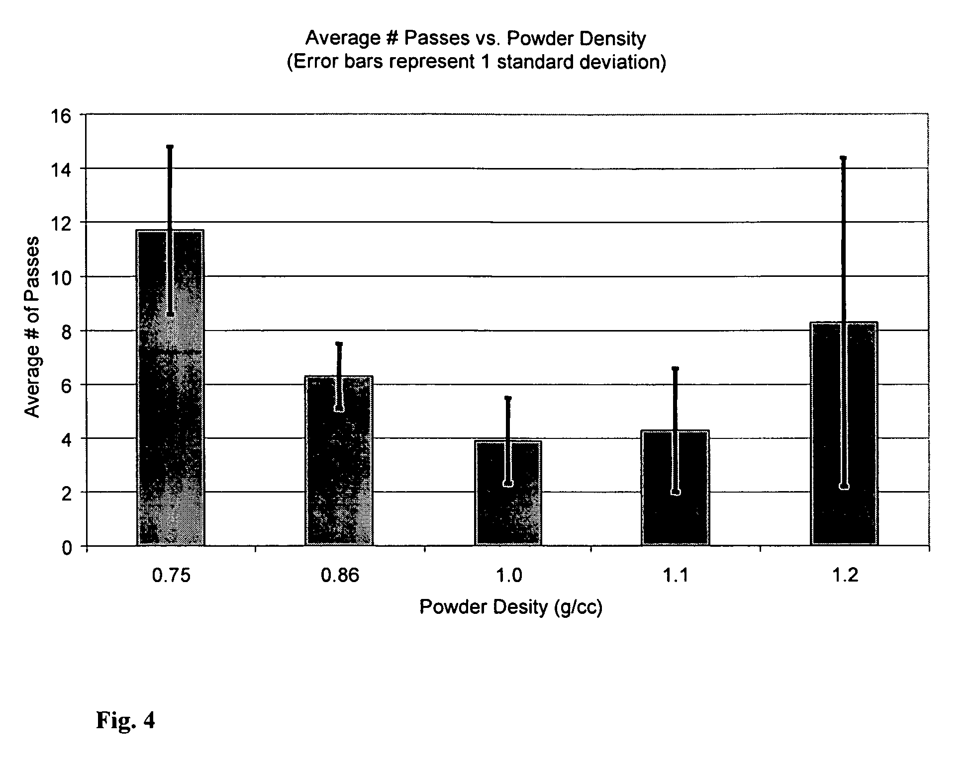
[0037]In order to determine the optimum compaction for a calcium phosphate powder, fifteen 20 mL mixing devices (syringes) with porous caps were each filled with 6.0 grams of calcium phosphate. The plungers were inserted into the barrel and compressed using a uniaxial testing machine until a given powder density was achieved. Three syringes were compressed to each of the following densities; 0.75, 0.86, 1.0, 1.1, 1.2 g / cc. Syringes were then tested by hydrating with 3.0 cc of saline using a 10 mL syringe and mixed by passing the powder and saline back and forth between the syringes until a smooth paste was achieved. The number of passes, or strokes, required to achieve complete mixing was recorded and averaged for each density. The results are shown in FIG. 4. A powder density of 1.0 g / cc was found to be optimal for this calcium phosphate.

example 2

[0038]To demonstrate the ability of the present device and its method of use to simplify preparation and to enhance injectability of a conventional calcium phosphate cement (CPC) the following study was performed.

[0039]Two CPC precursors; an amorphous calcium phosphate (ACP) (with Ca / P<1.5) and dicalcium phosphate dihydrate (DCPD) seeded with apatite (10-25% w / w) were prepared using a low temperature double decomposition technique. The two powders were mixed at a 1:1 ratio and milled in a high-energy ball mill for 3 hours. The resulting powder was filled into a syringe and connected to a second syringe filled with saline by means of a luer connector. The saline was injected into the powder at a liquid to powder (L / P) ratio of 0.5:1 and the mixture was then passed back-and-forth between the syringes until a uniform paste was formed (approximately 5 passes). The same cement mixed (with the same L / P) in a bowl with a spatula and then transferred into a syringe was used as a control. Th...


PUM


Abstract

Bone cement mixing and delivery device and methods are disclosed. The device includes a first tube / barrel (e.g., a syringe barrel) containing a bone cement powder and a second tube / barrel that can be filled with or that contains a liquid; the first and second tubes / barrels can be fluidly connected end-to-end such that there is fluid communication between the tubes / barrels. Also disclosed are methods of preparing the device for use, methods for forming a bone cement using the device, and methods and device design to extend the shelf life of the device.

Description

CROSS-REFERENCE TO RELATED APPLICATIONS[0001]This application claims priority under 35 U.S.C. §371 from international application PCT / US2008 / 010214, filed Aug. 28, 2008, which claims priority under 35 U.S.C. §119 from provisional application No. 60 / 966,579, filed Aug. 29, 2007. Both of these applications are incorporated by reference herein in their entirety.FIELD OF THE INVENTION[0002]The present invention relates to bone cement mixing devices, related systems, and methods of use thereof.BACKGROUND OF THE INVENTION[0003]Bone cements are used in orthopedic procedures for filling bone voids and repairing defects. They typically comprise a cement powder that is mixed with a liquid and manually applied to the defect site. The mixed cement may also be transferred into a delivery device and injected into the site. Current mixing and delivery systems rely on manual open mixing, such as a bowl and spatula, which can be messy and difficult to achieve uniformity. The open mixing and transfer...

Claims


Application Information

Patent Timeline
Patent Type & Authority Patents(United States)
IPC IPC(8): A61B17/88B01F5/06B01F15/02B01F11/00
CPCB01F5/0685B01F5/0688B01F11/0071B01F15/0201B01F15/0225A61B17/8827B01F25/4512B01F25/4521B01F31/65B01F35/71B01F35/7163
Inventor PALAZZOLO, ROBERTSUTARIA, MANISHTOFIGHI, ALIASSGHAR N.CHANG, TAK L.ROSENBERG, ARON D.
Owner ETEX
Why Eureka
Try Eureka