

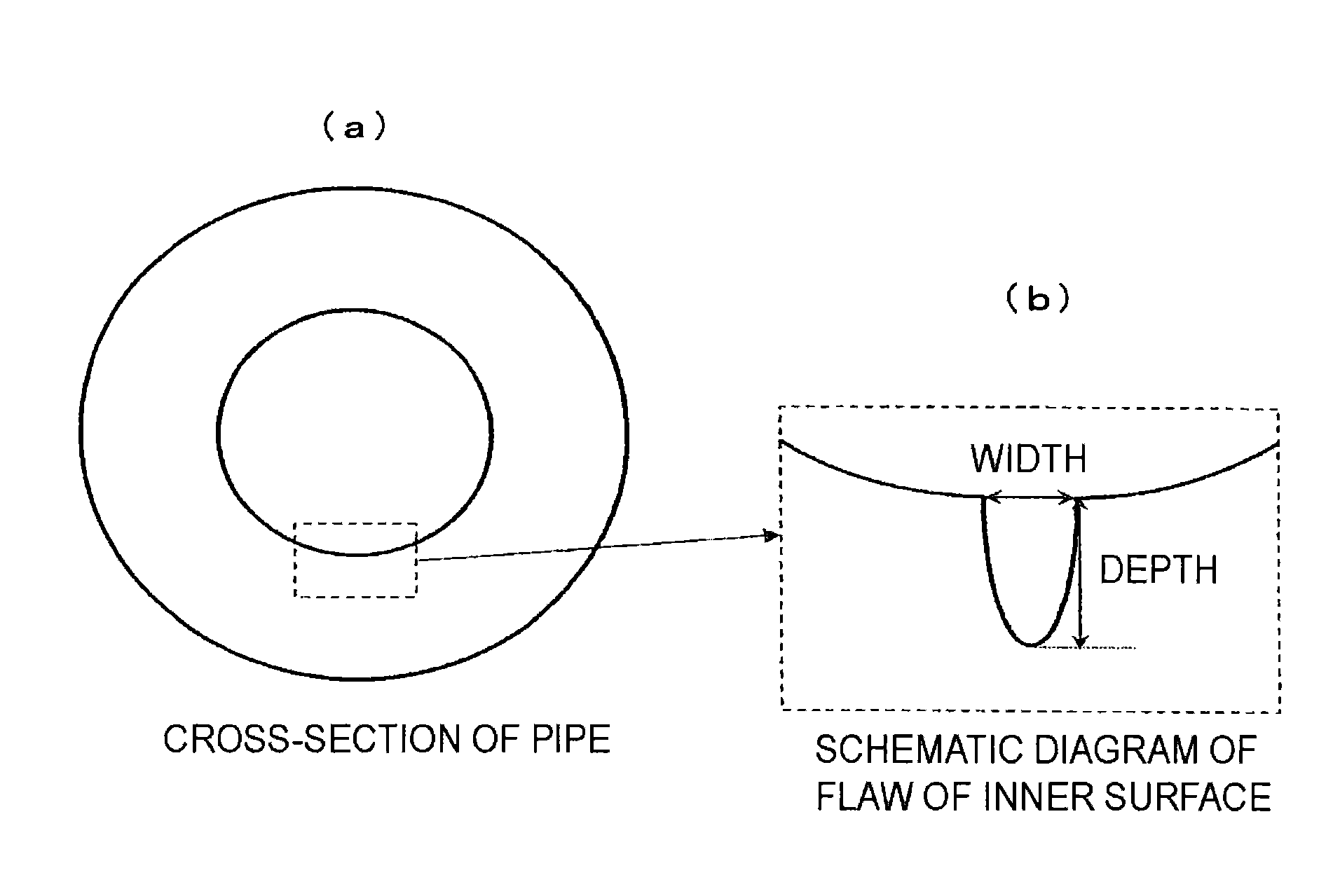
Hollow seamless pipe for high-strength spring
a high-strength spring and seamless pipe technology, applied in the direction of furnaces, heat treatment equipment, manufacturing tools, etc., can solve the problems of inability to secure the strength of springs to be formed, affecting the performance and affecting the quality of the hollow seamless pipe. , to achieve the effect of sufficient fatigue strength
- Summary
- Abstract
- Description
- Claims
- Application Information
AI Technical Summary
Benefits of technology
Problems solved by technology
Method used
Image

Examples
examples
[0076]Various kinds of molten steels (medium carbon steels) having the chemical component compositions shown in Table 1 described below were each melted by a usual melting method. The molten steels were cooled, followed by bloom rolling to form billets having a cross-sectional shape of 155 mm×155 mm. These billets were formed into round bars having a diameter of 150 mm by hot forging, followed by machine working, thereby preparing extruded billets. In Table 1 described below, REM was added in a form of a misch metal containing about 20% of La and about 40% to 50% of Ce. In Table 1 described below, “−” shows that no element was added.
[0077]
TABLE 1SteelChemical Component Composition (Mass %)SpeciesCSiMnPSNAlCrNiCuMoA0.402.501.000.0050.0050.00300.03001.050.450.20—B0.411.700.150.0030.0030.00200.02501.000.300.15—C0.421.800.250.0080.0080.00300.03000.950.200.20—D0.441.910.200.0060.0060.00400.03201.010.620.25—E0.451.700.350.0090.0090.00500.03000.500.200.10—F0.451.750.700.0150.0150.00300.002...
PUM
| Property | Measurement | Unit |
|---|---|---|
| diameter | aaaaa | aaaaa |
| width | aaaaa | aaaaa |
| width | aaaaa | aaaaa |
Abstract
Description
Claims
Application Information