Ion mobility analyzer, combination device thereof, and ion mobility analysis method

a technology of mobility analyzer and ion, which is applied in the direction of instrumentation, particle separator tube details, tube electrostatic deflection, etc., can solve the problems of difficult control of drift gas in the axial and radial directions, difficult improvement of ion separation ability, and low resolution, so as to reduce gas pressure difference, reduce ion loss, and good ion separation

Active Publication Date: 2016-08-30
SHIMADZU CORP
View PDF29 Cites 8 Cited by
  • Summary
  • Abstract
  • Description
  • Claims
  • Application Information

AI Technical Summary

Benefits of technology

[0016]In the device, if we select the drift electric field as the reference frame, ions in the drift field will have an extra directional velocity relative to the surrounding background gas. The velocity is always opposite to the direction of the drift electric field if taking the ion mobility analyzer as the reference frame. That is to say, in an experimental environment filled with collisional gas having relatively low speed or essentially static state, in the reference frame of rotating field it can be regarded ions are equivalently encountered with the opposite ‘drift gas’ which has an opposite movement direction with the rotating field in the reference frame of ion mobility analyzer. Since the velocity and direction of the ‘drift gas’ are actually decided by the drift field, it is easy to realize the stable adjustment of the velocity of ‘drift gas’ from zero to ten thousands of meters per second by controlling power supply. Thus, if ions don't leave the ion drift electric field, ions will find an appropriate position in the electric field where they have a same ion drift velocity resulting from the combined effect of the electric field and collisional gas with the velocity of drift electric field so ions with certain mobility can be held for a long time in the ion drift electric field with a finite length and separated from other ions with different ion mobility. Meanwhile, it is different from the travelling wave ion mobility spectrometry because in the analysis process of ion mobility, the ions are not affected by the travelling wave voltage that fast sweeps over the ion drift regions and the wavefront of drift field. Thus, there is no rapid acceleration or deceleration process in the motion and it reduces the influence of clustering and declustering on the result of ion mobility measurement. Hence, the ion mobility achieved with this method is well consistent with the result of tradition drift tube and it makes good comparison of data. Please note the RF voltage for common ion guide transmission is not always necessary in this device, because the ion focusing during the ion mobility drift separation can be achieved by nonlinear field, periodic focusing or applying RF on and off with a duty-cycle.
[0047]Moreover, the invention has purposed a tandem ion mobility analyzing method with mass spectrometer, to form a two dimensional analysis of IMS and MS. Furthermore, the invention has purposed a serial ion mobility analyzing method whose characteristic is to apply different analyzing conditions on the different parts of ion mobility analyzer or multiple ion mobility analyzing devices. Theses different conditions include at least one of the following: type and distribution of background collision gas, background pressure, temperature and humidity of background gas, the velocity of drift electric field, the change in drift electric field step, radial confinement voltage wave shape and speed of background collision gas. It creates at least two different ion separation or distribution processes according to ion mobility. These two different separation and distribution processes create orthogonal 2D mobility separation so as to improve the selectivity of ion mobility analyzing method.

Problems solved by technology

However, due to the complexity of separation mechanism, its mobility spectrum is hard to take a clear interpretation, there is no extensively recognized way in interpreting such mobility spectrum.
However, because of the limitation of the structure of DMA itself and the affection of ion diffusion, the ability of separation of ions is difficult to improve, Usually, tens of resolution or even less its maximum yield so this is not quite an area people are interested in.
However, the control of drift gas in the axial and radial directions can be tough so the resolution is relatively low.
However, this method can't constrict the diffusion of ions in radial directions, the huge loss of ions makes detection difficult.
Other ions are blown off because of inappropriate mobility.
However, it is very difficult to introduce ions and also requires very stable drift gas and electric field.
Moreover, its characteristics time consuming makes serious ion diffusion that consequently ruins the high sensitivity detection.
At last, there is no practical prototype developed.
The result was glad and high resolution was obtained but there is no further experimental result, Obviously, the experiment of this kind must be very difficult to do, Wenjian Sun has announced a device that can be used to separate or accumulate ions in the World Patent WO2010060380.
The difference of this ion mobility analyzer from Ichimura's counter flow ion mobility device is that this device does not capture ions at all but uses a counter flow of gas to counteract the force exerted by the electric field.
It can not only improve the resolution but also expand the time width of ion peak which extremely elevates the sampling frequency of TOF.
However, because of the limited length of the drift region, the device's maximum resolution is limited, Although elevating gas pressure can help broaden the retention time of ions and also improve the device's performance, the ion diffusion in the radial direction is out of control.
In facts, it is very hard to obtain the stable drift gas and electric field.
However, due to the mechanism of separation by travelling wave ion mobility spectrometry and the complexity of separation process, it is hard to get the information about ion mobility or collisional cross section directly from the spectrum.
However, because of long separation time and ion diffusion in the radial direction, only one kind of ions can survive.
The loss of ions is huge which makes sensitivity relatively low.
This may cut away part of the ion cloud and bring uncertain effect on the drift time of ions.
Unfortunately, drift gas can't be adjusted in a fast, cheap, stable and accurate way like electric field so ion mobility storage device with high resolution is difficult to achieve.

Method used


Image

  • Ion mobility analyzer, combination device thereof, and ion mobility analysis method
  • Ion mobility analyzer, combination device thereof, and ion mobility analysis method
  • Ion mobility analyzer, combination device thereof, and ion mobility analysis method

Examples


embodiment 1

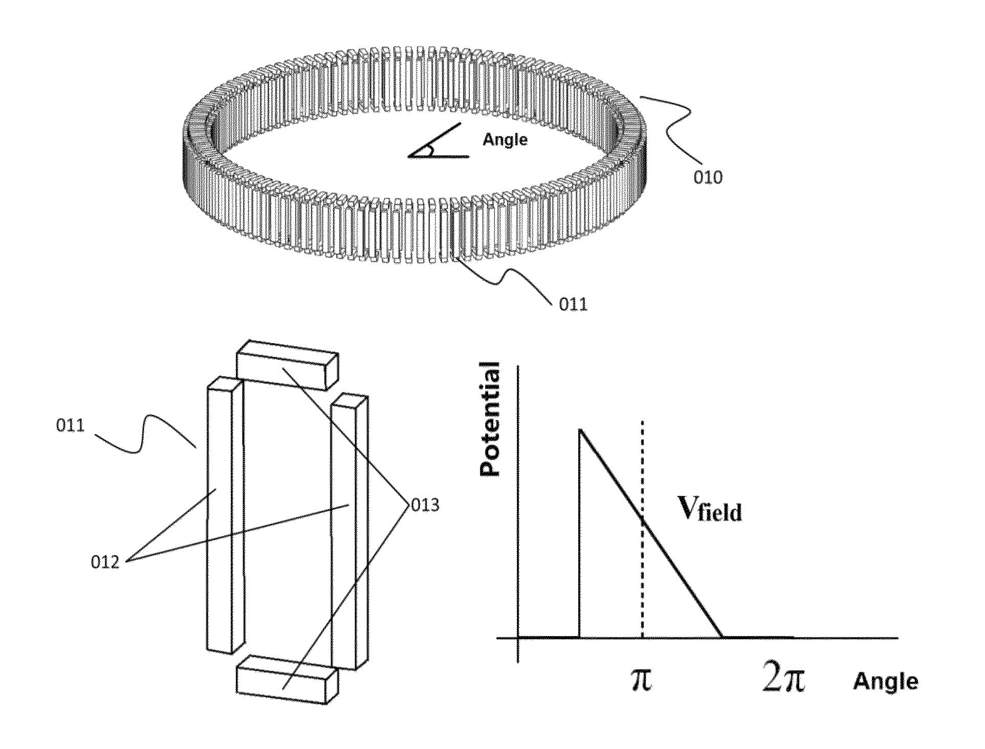
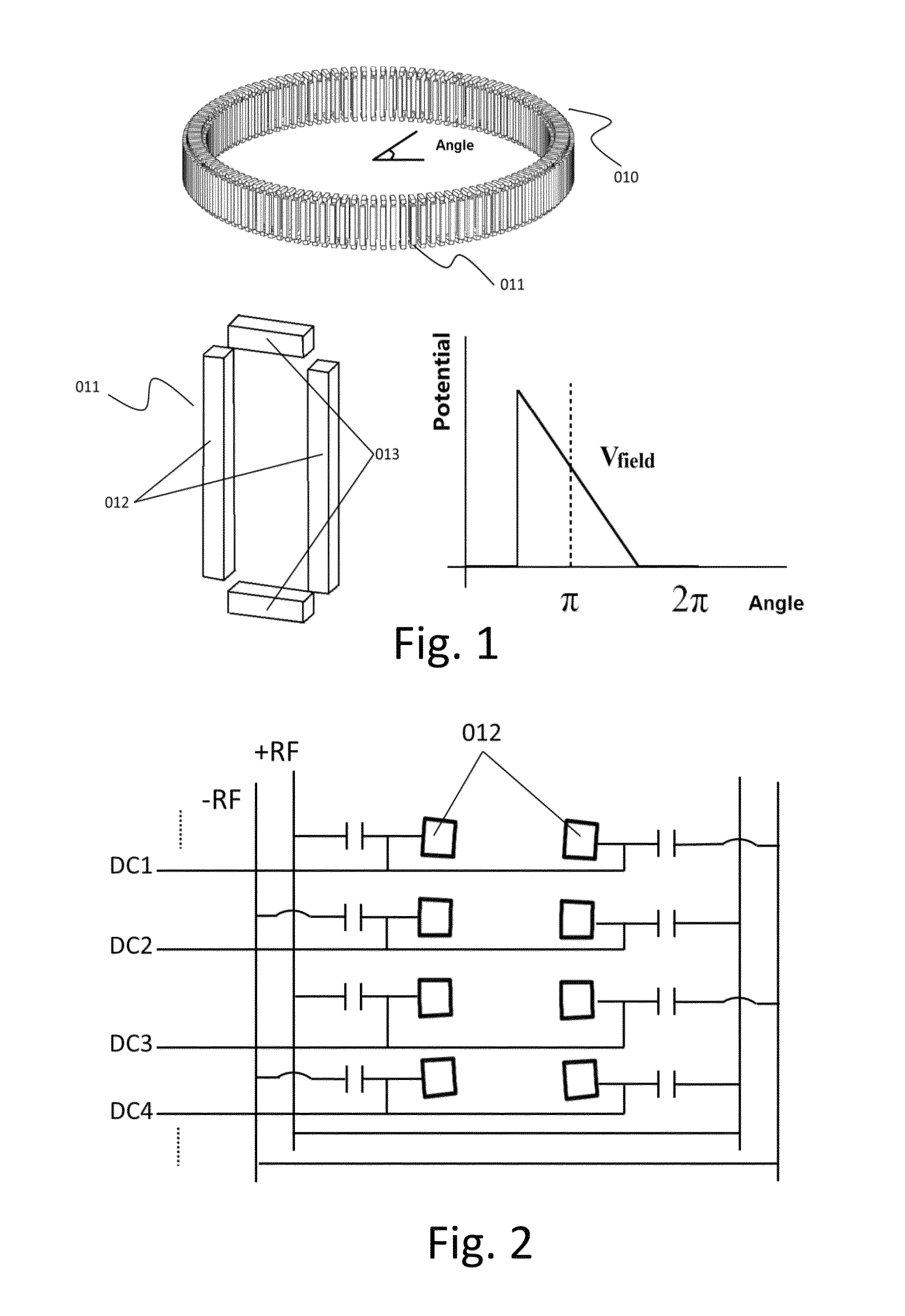
[0074]As a preferred structure of the ion mobility analyzer 010, the component structure is a closed circular pattern composed of a set of controlled electrode components. Each individual electrode module is composed of a pair of side electrodes 012 and a pair of endcap electrodes 013. The ion mobility analyzer 010 is filled with the gas of certain pressure. The pressure is around 100 Pa-3000 Pa and the gas does not flow in ion mobility analyzer 010. The gas stays static or close to static state. In order to avoid the disturbance of air inlet and outlet to the gas inside analyzer 010, the gas should keep a distance from air inlet and outlet. When it comes to separate ions that enter the ion mobility analyzer, the DC electric potential distribution with linear change is applied on the side electrode 012 corresponding to each individual electrode component unit 011. Also, it needs to rotate in the direction where the angle increases. The rotating speed Vfield ranges from hundreds of m...

embodiment 2

[0079]This example shows another approach to create drift electric field of moving ions. As shown in FIG. 16, in the arrangement of multiple circle electrodes that are parallel to each other, for each electrode, periodic switching waveform was applied between a pair of voltage level with frequency from 10 KHz to 10 MHz, among these, the phase of waveforms applied on adjacent electrodes e.g. 1601 and 1602 are different. Therefore, the trapping fields for ions can be generated. Slightly different from the example 1, in such device the additional drift voltage gradient is not required. It was replaced with the average pseudo-potential voltage value Vpseudo=DV1+(1−D)V2, in which D is the duty cycle ratio of the higher potential voltage V1, and V2 is the lower potential value.

[0080]One advantage of the design is the pseudo potential voltage value can be adjusted by the duty cycle, Usually, this way of control can be realized through High Speed Digital Electric Circuit, Digital Signal Pro...

embodiment 3

[0086]As a simplification to the previous embodiments, at least one part of the electrode can be shared among different parallel tunnel structures to form a simple ion mobility analyzer array. This helps simplify the structure of capacitor and devices. FIGS. 18A and 18B show the structure of the ion mobility analyzer array in shared electrodes form constructed by circular and long electrode sets. 1801 and 1802 are two shared electrode parts of the structures. Other than that, as shown in FIG. 18C, the constraint electrodes like 1803, 1804 and 1805 with opposite polarity in different parallel tunnels can be treated as shared constraint electrodes of the adjacent ion mobility analyzer. The each parallel tunnel structure can be separated only by the pseudo potentials. Therefore, the analyte ions can be transmitted between each other tunnels without any hitting-wall loss.

[0087]In order to improve the separation effect of the analyzing approach used in the device, in analyzing science, t...


PUM

PropertyMeasurementUnit
frequencyaaaaaaaaaa
frequencyaaaaaaaaaa
pressureaaaaaaaaaa

Abstract

An ion mobility analyzer, combination device thereof, and ion mobility analysis method. The ion mobility analyzer comprises an electrode system that surrounds the analytical space and a power device that attaches to the electrode system an ion mobility electric potential field that moves along one space axis. During the process of analyzing mobility of ions to be measured, by always placing the ions to be measured in the moving ion mobility electric potential field, and keeping the movement direction of the ion mobility electric potential field consistent with the direction of the electric field on the ions to be measured within the ion mobility electric potential field, theoretically a mobility path of an infinite length can be formed so as to distinguish ions having mobility or ion cross sections that have very small differences.

Description

CROSS-REFERENCE TO RELATED APPLICATIONS[0001]This application is a continuation application of International Patent Application No. PCT / CN2013 / 001508, filed Dec. 6, 2013, which itself claims the priority to Chinese Patent Application No. 201210530144.9, filed Dec. 10, 2012 in the State Intellectual Property Office of P.R. China, which are hereby incorporated herein in their entireties by reference.FIELD OF THE INVENTION[0002]The present invention relates generally to ion mobility spectrometry, and more particularly to a device for ion analyze that can realize fast separation, accumulation and detection.BACKGROUND OF THE INVENTION[0003]The background description provided herein is for the purpose of generally presenting the context of the present invention. The subject matter discussed in the background of the invention section should not be assumed to be prior art merely as a result of its mention in the background of the invention section. Similarly, a problem mentioned in the back...

Claims


Application Information

Patent Timeline
Patent Type & Authority Patents(United States)
IPC IPC(8): H01J49/00G01N27/62H01J49/40H01J49/34H01J49/22G01N27/622
CPCG01N27/622H01J49/004H01J49/22G01N27/624G01N27/623
Inventor JIANG, GONGYUCHENG, YUPENGZHANG, XIAOQIANGSUN, WENJIAN
Owner SHIMADZU CORP
Why Eureka
Try Eureka