Polarization beam splitter and optical device

a polarization beam and optical device technology, applied in the direction of optical elements, optical radiation measurement, instruments, etc., can solve the problems of difficult to miniaturize a chip, difficult for the silica waveguide to increase a relative index difference, etc., and achieve high productivity.

Active Publication Date: 2016-10-04
NEC CORP
View PDF4 Cites 2 Cited by
  • Summary
  • Abstract
  • Description
  • Claims
  • Application Information

AI Technical Summary

Benefits of technology

[0010]According to the present invention, it is possible to provide a polarization splitter and an optical device with high productivity.

Problems solved by technology

However, it is difficult for the silica waveguide to increase a relative index difference between a core and a clad.
Accordingly, the minimum bend radius of the waveguide is of the order of mm, and thus it is difficult to miniaturize a chip.

Method used


Image

  • Polarization beam splitter and optical device
  • Polarization beam splitter and optical device
  • Polarization beam splitter and optical device

Examples


Embodiment Construction

[0020]Exemplary embodiments of the present invention will be described with reference to the accompanying drawings. The following exemplary embodiments are examples of the present invention, and the present invention is not limited to the following exemplary embodiments. The same reference numerals in the specification and the drawings denote the same components.

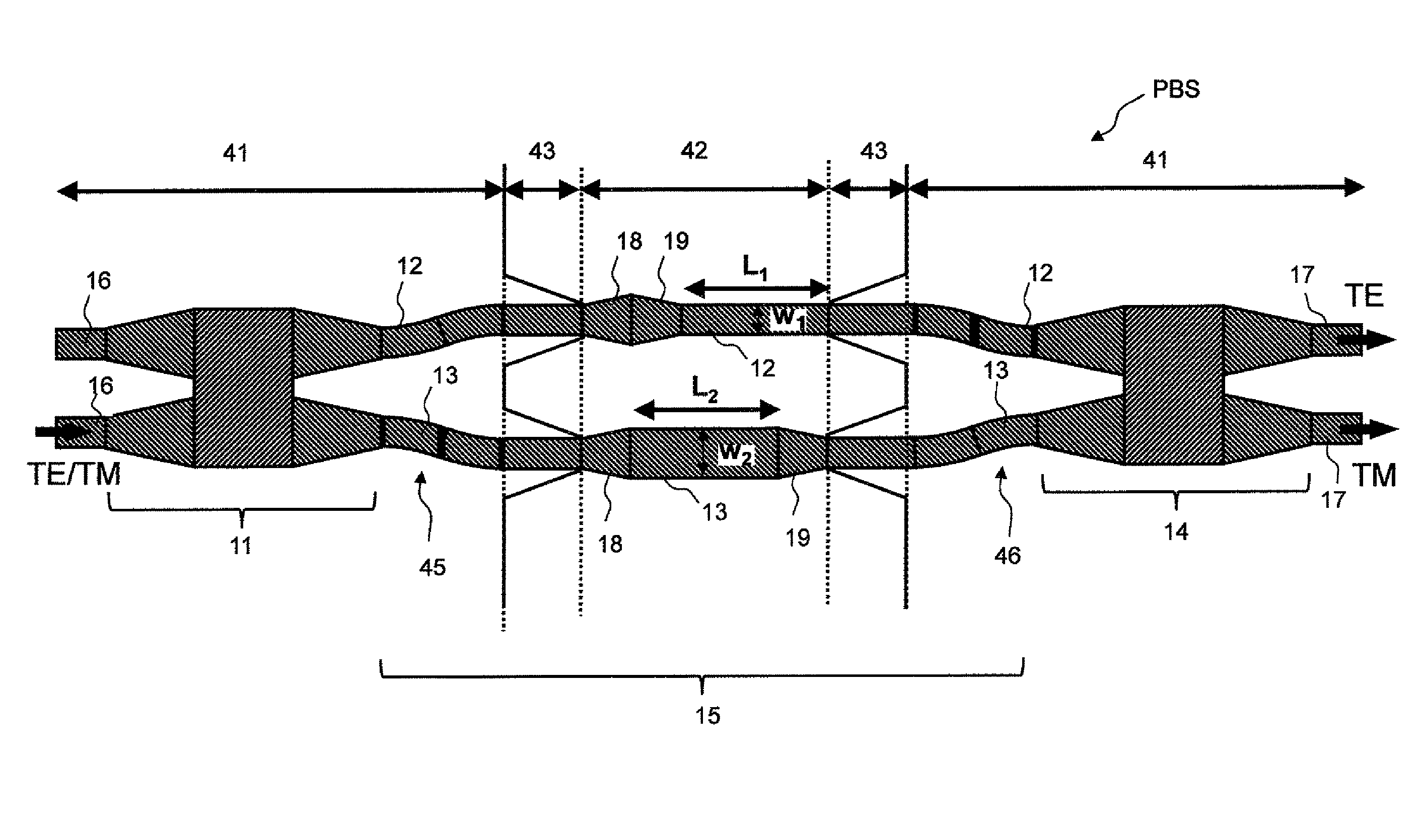
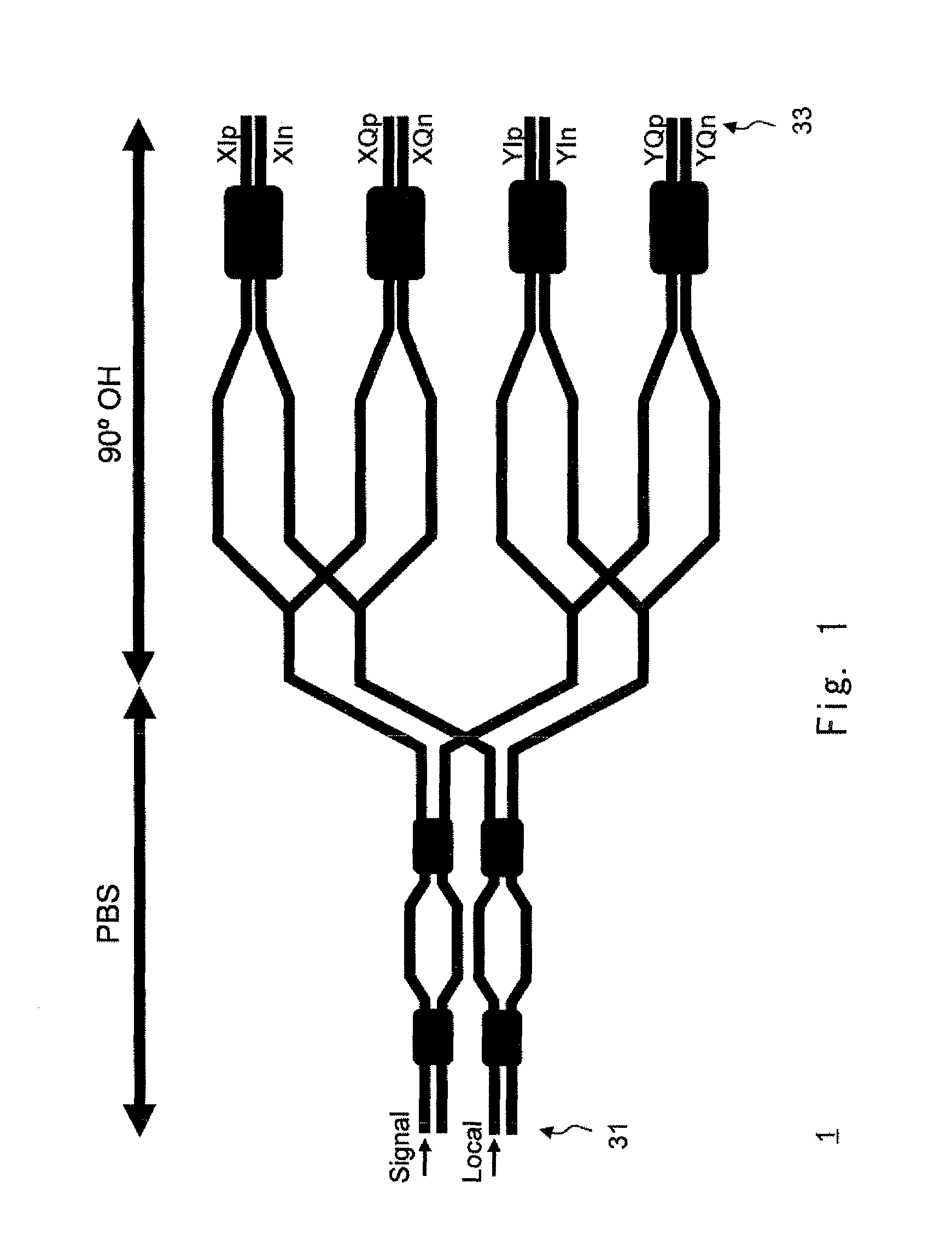
[0021]FIG. 1 is a schematic view showing a coherent mixer element 1 used for digital coherent communication. The coherent mixer element 1 is, for example, a planar lightwave circuit (PLC), and includes a polarization beam splitter PBS and a 90-degree optical hybrid 90° OH. The polarization beam splitter PBS is a circuit having a polarization beam splitting function. The polarization beam splitter PBS is, for example, a Mach-Zehnder interferometer that uses the birefringence of arm waveguides. The 90-degree optical hybrid 90° OH is a circuit (coherent mixer circuit) having a function for retrieving phase information.

[0022]The...


PUM

PropertyMeasurementUnit
refractive indexaaaaaaaaaa
thicknessaaaaaaaaaa
thicknessaaaaaaaaaa

Abstract

Provided are a polarization beam splitter and an optical device with high productivity. A polarization beam splitter (PBS) according to an exemplary embodiment of the present invention includes: a demultiplexer (11) that is formed of a rib waveguide (50) and demultiplexes input light into first input light and second input light; a multiplexer (14) that is formed of the rib waveguide (50) and multiplexes the first input light and the second input light that are obtained by demultiplexing the input light by the demultiplexer (11); a first arm waveguide (12) that is formed of a channel waveguide (51) and guides the first input light to the multiplexer (11); and a second arm waveguide (13) that is formed of the channel waveguide (51), generates a phase difference in the first input light propagating through the first arm waveguide, and guides the second input light to the multiplexer (14).

Description

CROSS-REFERENCE TO RELATED PATENT APPLICATIONS[0001]This application is a National Stage Entry of International Application No. PCT / JP2013 / 006763, filed Nov. 19, 2013, which claims priority from Japanese Patent Application No. 2013-028866, filed Feb. 18, 2013. The entire contents of the above-referenced applications are expressly incorporated herein by reference.TECHNICAL FIELD[0002]The present invention relates to a polarization beam splitter and an optical device.BACKGROUND ART[0003]In recent years, in regard to ultrahigh-speed communications exceeding 100 Gb / second, studies have been vigorously conducted on digital coherent communication by Dual Polarization Differential Quadrature Phase Shift Keying (DP-QPSK) excelling in wavelength use efficiency, receiving characteristics, and dispersion compensation capability. A receiver for DP-QPSK system requires a function to split an optical signal into polarized waves, and a 90-degree optical hybrid function for retrieving phase informa...

Claims


Application Information

Patent Timeline
Patent Type & Authority Patents(United States)
IPC IPC(8): G02B6/00G02B6/126G02B6/293G02F1/035G01J9/02G02B6/122G02B6/12
CPCG02B6/126G01J9/02G02B6/1228G02B6/2938G02B6/29352G01J2009/0288G02B6/122G02B2006/121G02B2006/12097
Inventor MATSUMOTO, TAKASHI
Owner NEC CORP
Why Eureka
Try Eureka