Radio wave-transmitting decorative film and decorative member using same

a technology of decorative film and metallic gloss, which is applied in the field of radio wave-transmitting decorative film having metallic gloss and a decorative member using the same, can solve the problems of low productivity, tin is prone to oxidation, and low productivity, and achieves excellent stretch moldability, low cost, and not easily disappearing

Active Publication Date: 2016-11-15
SHIN-ETSU POLYMER CO LTD
View PDF47 Cites 1 Cited by
  • Summary
  • Abstract
  • Description
  • Claims
  • Application Information

AI Technical Summary

Benefits of technology

[0026]The radio wave-transmitting decorative film of the invention has radio wave transmissibility, a mirror-like metallic gloss which does not easily disappear, excellent stretch moldability, and low cost.
[0027]The decorative member of the invention has radio wave transmissibility, a mirror-like metallic gloss which does not easily disappear, an excellent external appearance in a portion where the decorative film of the corner portion is stretched, and low cost.

Problems solved by technology

(iv) The frequency of radio waves used in communication devices (wireless PAN such as Bluetooth, UWB, and ZigBee) has been shifting to a high frequency range of from millimeter waves to microwaves, at which radio waves are readily affected by the decorative members, and thus these devices are prone to functional disorders.
Therefore, as to whether a product using the decorative film of (1) does not impede the straightness of the radio waves, or other disorders do not occur, all of the products using the decorative film are required to be inspected, and therefore it has a low productivity.
In addition, tin is prone to oxidation, chlorination, or the like, as a result of which the metallic gloss thereof is lost over time.
On the other hand, indium is not readily available and highly expensive.
The decorative film of (2) has a low productivity and the high cost of a laminated film.
In addition, the heating stretch moldability is deteriorated and therefore the decorative film cannot be formed into a desirable shape.
Further, through hot forming, the refractive index of the decorative film and the balance of the respective layers are changed, and therefore a loss of metallic gloss occurs.

Method used


Image

  • Radio wave-transmitting decorative film and decorative member using same
  • Radio wave-transmitting decorative film and decorative member using same
  • Radio wave-transmitting decorative film and decorative member using same

Examples


example 1

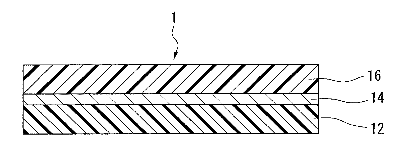
[0187]The surface of acryl film, as a first polymer film 12, having a thickness of 50 μm, was subjected to physical vapor deposition using a DC sputtering apparatus with the following target to form a light-reflecting layer 14.

[0188]An alloy composed of silicon and aluminum which was doped with boron (aluminum proportion: 60 volume %, amount of doped boron: approximately 10−7 mol %) was used as the target. The reflectance of the elemental form of aluminum is 87.6%.

[0189]Then, acryl film, as a second polymer film 16, having a thickness of 50 μm, was subjected to thermal lamination on the surface of the light-reflecting layer 14 to obtain a decorative film 1 shown in FIG. 1.

[0190]With respect to the obtained decorative film 1, the thickness of the light-reflecting layer 14, the amounts of transmission attenuation (S21) at 1 GHz and 3 GHz, the reflectance of visible light entered from first polymer film 12, the surface resistivity, and the average surface roughness were measured. In ad...

example 2

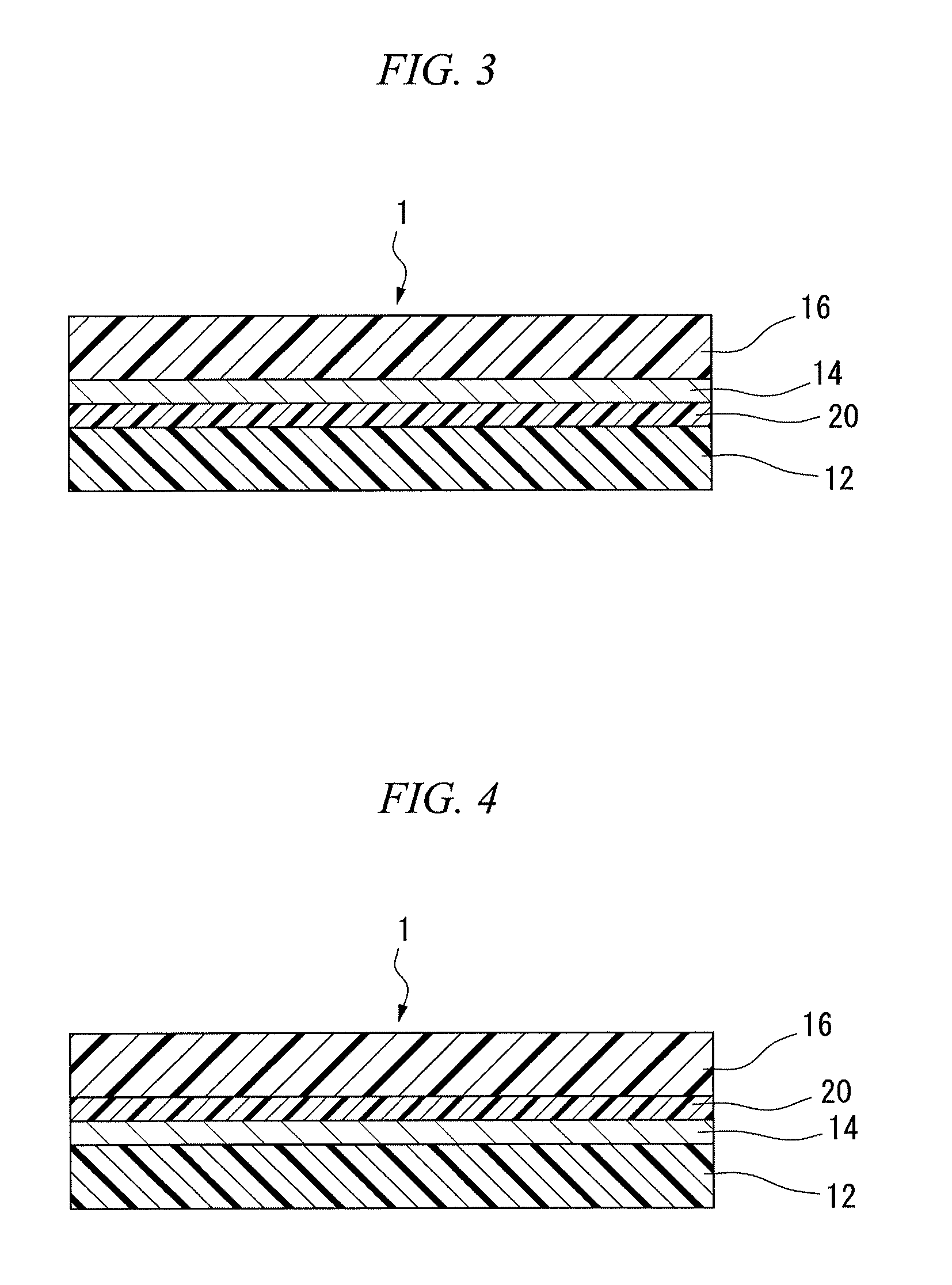
[0193]The surface of polycarbonate film having a thickness of 100 μm as a first polymer film 12 was subjected to physical vapor deposition at a flow of nitrogen gas of 0.5 sccm, to form a light-reflecting layer 14 of which a portion was formed into ceramics, using a DC sputtering apparatus with the same target as Example 1.

[0194]Then, a polyolefin chloride layer was laminated on the surface of black ABS film having a thickness of 100 μm as a second polymer film 16 and the polyolefin chloride layer was used as an adhesive, which was adhered to light-reflecting layer 14 to obtain a decorative film 1.

[0195]With respect to the obtained decorative film 1, the thickness of the light-reflecting layer 14, the amounts of transmission attenuation (S21) at 1 GHz and 3 GHz, the reflectance, the surface resistivity, and the average surface roughness were measured. In addition, the external appearance of the decorative film 1 was observed. The results are shown in Table 1.

[0196]The decorative fil...

example 3

[0197]A laminate of a copolymerizable polyester film (manufactured by Toyobo Co., Ltd., trade name Softshine) having a thickness of 25 μm and an acryl film having a thickness of 50 μm was prepared as a first polymer film 12.

[0198]On the surface of the copolymerizable polyester film, oxygen plasma processing was performed under conditions of power: 500 W, time: 2 minutes, reaching vacuum degree: 6×10⁻¹ Pa, oxygen flow rate: 15 sccm.

[0199]On the surface treated with plasma, physical vapor deposition was performed using an alloy (aluminum proportion: 70 volume %) of silicon and aluminum by a DC sputtering apparatus as a target, to form a light-reflecting layer 14.

[0200]Black ABS film was adhered in a manner similar to Example 2, to obtain a decorative film 1.

[0201]With respect to the obtained decorative film 1, the thickness of the light-reflecting layer 14, the amounts of transmission attenuation (S21) at 1 GHz and 3 GHz, the reflectance, the surface resistivity, and the average surfa...


PUM

PropertyMeasurementUnit
thicknessaaaaaaaaaa
thicknessaaaaaaaaaa
surface roughnessaaaaaaaaaa

Abstract

Disclosed are a low-cost radio wave-transmitting decorative film which has excellent stretch moldability, radio wave transmissibility, and mirror-like metallic gloss that does not easily disappear, and a decorative member employing the radio wave-transmitting decorative film. Specifically disclosed are a decorative film which includes a first polymer film, a second polymer film, and a light-reflecting layer which is arranged between the polymer films and formed by the physical vapor deposition of an alloy of silicon and a metal, and a decorative member in which the decorative film is provided on the surface of a base.

Description

CROSS-REFERENCE TO RELATED APPLICATIONS[0001]The present application is a 35 U.S.C §371 national phase conversion of PCT / JP2010 / 001826, filed Mar. 15, 2010, which claims priority of Japanese Patent Application No. 2009-064568, filed Mar. 17, 2009, the contents of which are incorporated herein by reference. The PCT International Application was published in the Japanese language.TECHNICAL FIELD[0002]The present invention relates to a radio wave-transmitting decorative film having metallic gloss and a decorative member using the same.BACKGROUND ART[0003]From the viewpoint of design properties, metallic decorative members, in particular, decorative members having a mirror-like metallic gloss have been widely used in the casing of a mobile phone; the button of a switch; the casing of a watch; and the radiator grill, bumper, panel or the like of a vehicle.[0004]As such decorative members, a decorative member that transmits radio waves (microwaves or the like) without adversely affecting ...

Claims


Application Information

Patent Timeline
Patent Type & Authority Patents(United States)
IPC IPC(8): B32B9/04C23C14/20B32B27/08
CPCC23C14/20B32B27/08B32B2250/24B32B2255/10B32B2255/205B32B2307/416B32B2307/20B32B27/302B32B27/32B32B2307/412B32B27/365B32B2451/00B32B7/12B32B2307/732B32B27/308B32B27/304B32B27/40B32B2307/406B32B27/36B32B27/306B32B27/325
Inventor KAWAGUCHI, TOSHIYUKITAHARA, KAZUTOKISAGA, TSUTOMU
Owner SHIN-ETSU POLYMER CO LTD
Why Eureka
Try Eureka