

Method for detecting target materials using nuclear quadrupole resonance
a target material and nuclear quadrupole resonance technology, applied in the field of detection of target materials, can solve the problems of large amount of power required for rf pulses, process about, problems and issues may still arise, etc., and achieve the effect of effectively measuring the nqr emission and optimizing power consumption
- Summary
- Abstract
- Description
- Claims
- Application Information
AI Technical Summary
Benefits of technology
Problems solved by technology
Method used
Image


Examples
second embodiment
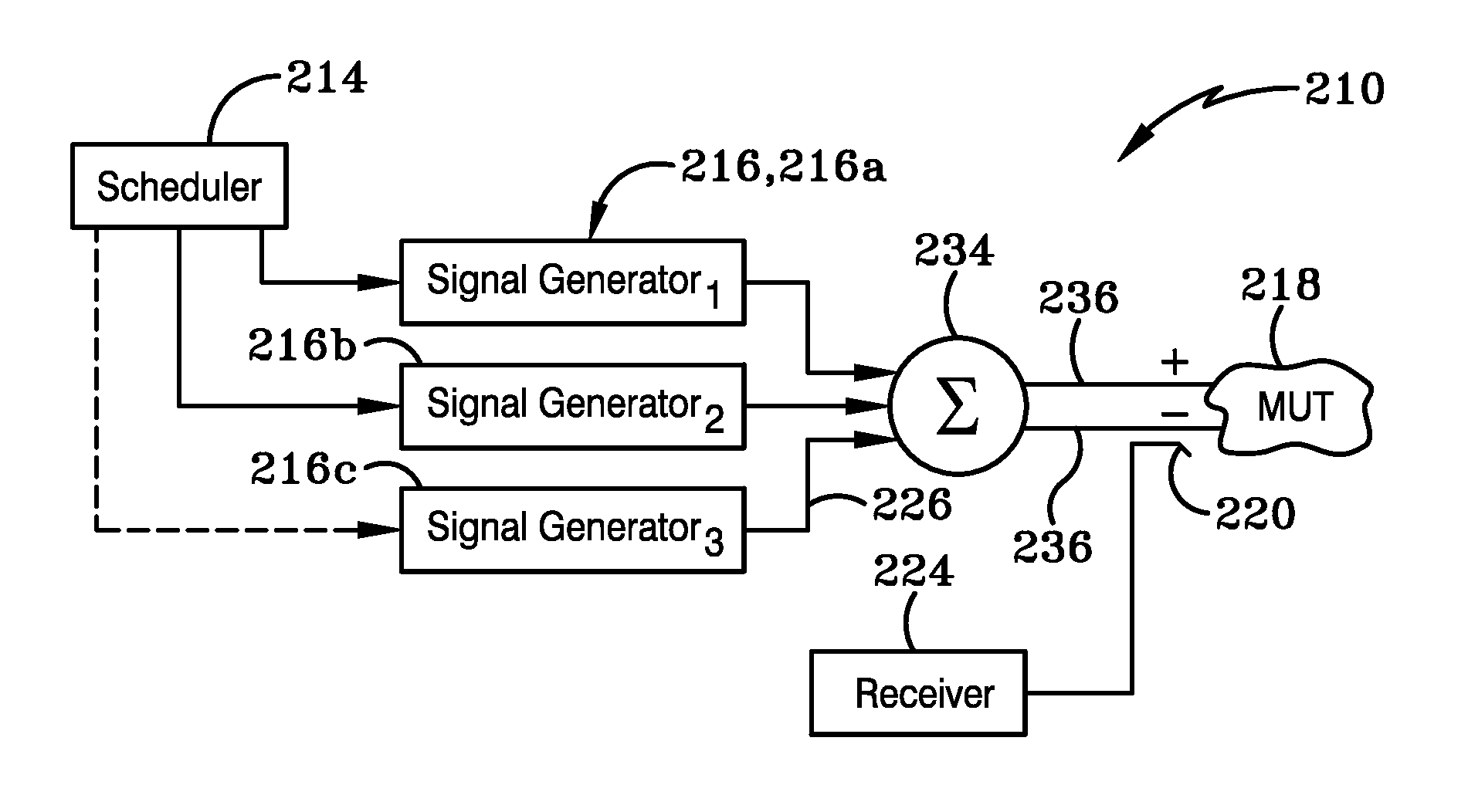
[0060]As shown in FIG. 3, a second embodiment system 210 may include a scan schedule 214, a signal generator 216, sample material 218, a directional coupler 220, a receiver 224, transmission lines 226, a mixer or diplexor 234, and twin lead lines 236. Scheduler 214 is in communication with generator 216. As shown in FIG. 3, generator 216 can be furcated into multiple generators, shown as 216a, 216b, and 216c, respectively, each able to broadcast a continuous wave irradiation signal at a given frequency. These three signals are carried via transmission lines 226 to mixer 234 and broadcasted to material 218 via twin lead lines 236. Return frequencies are transmitted through the directional coupler 220 to a receiver 224. Receiver 224 is preferably a twenty-bit receiver having a dynamic range receiving capacity between about 0 to about 90 db. In this system, the multiple excitation frequencies are directly coupled to a single probe within the measurement chamber. NQR emissions from the ...
third embodiment
[0062]As shown in FIG. 4, a third embodiment system 310 to detect explosives using NQR includes a random scan scheduler 314, a pulsed signal generator 316, sample material 318, a directional coupler, an amplifier 322 and a receiver 324. Signals are transmitted through transmission lines 326 through amplifier 322 and broadcasted into sample material 318. Return frequencies are transmitted through the directional coupler 220 to a receiver 224. The scheduler that controls the frequencies and pulses transmitted by the signal generator selects the frequencies rather randomly to prevent an independent observer that might be monitoring the test frequencies and their sequence of transmission pulses from being recorded for later application of countermeasures to prevent the system from detecting the targeted material in the MUT or simply by selecting a material that is not being checked for on that particular day for expediency purposes.
[0063]Rather than providing a continuous wave irradiati...
fourth embodiment
[0066]With primary reference to FIG. 5, a fourth embodiment system 410 includes a library 412, a power control 414, a signal generator 416, sample material 418, a directional coupler 420, an amplifier 422, a correlator 424, transmission lines 426, a mixer or diplexer 434 for transmitting signals via twin leads 436 to sample material 418. As shown in FIG. 5, power control may be separated into individual control units 414a, 414b, and 414c connected to first signal generator 416a, second signal generator 416b, and third signal generator 416c, respectively. Generators 416a-c transmit signals to mixer 434 for transmitting signals via twin leads 436 to sample material 418. Directional coupler 420 permits return signals from sample material 418 to be sent through amplifier 422 to correlator 424 via transmission lines 426. Library 412 is operatively connected to correlator 424.
[0067]In accordance with another aspect of the invention as herein described above, the system 410 provides a syst...
PUM
| Property | Measurement | Unit |
|---|---|---|
| relaxation time | aaaaa | aaaaa |
| relaxation time | aaaaa | aaaaa |
| relaxation times | aaaaa | aaaaa |
Abstract
Description
Claims
Application Information