Methods, systems and apparatus of an all-optics ultrasound sensor

an all-optics, ultrasound sensor technology, applied in the field of microscopy, can solve the problems of limiting lateral and axial resolution, difficult to integrate pam with a conventional high-resolution optical microscopic system, and reducing the lateral resolution. , to achieve the effect of convenient deformation

Active Publication Date: 2016-12-06
NORTHWESTERN UNIV
View PDF6 Cites 4 Cited by
  • Summary
  • Abstract
  • Description
  • Claims
  • Application Information

AI Technical Summary

Problems solved by technology

However, previous efforts to integrate PAM with confocal microscopy and optical coherence tomography were found to have rather limited lateral and axial resolutions.
In prior approaches, lateral resolution was fundamentally limited by the small numerical aperture (NA) being used due to the long working distance required to accommodate sizeable piezoelectric detectors.
Due to the limitations of these piezoelectric detectors, it becomes technically difficult to integrate PAM with a conventional high-resolution optical microscopic system in which the working distance of an objective lens is normally less than 1 mm.
However, the sizeable and opaque piezoelectric ultrasonic detectors commonly used in PAM impose a serious constraint.
Although traditional piezo-electric ultrasonic transducer technologies have advanced tremendously over the past decade, these transducers still suffer from at least two key limitations: (1) opaque and relatively large size packaging and (2) limited detection bandwidth.
First, traditional piezo-electric ultrasonic transducer packaging can be large because piezo-electric materials usually need backing and housing to achieve optimal performance.
The final packaged size cannot be too thin, and piezo-electric materials and backing materials are not transparent to light.
Moreover, due to the finite size to achieve optimal sensitivity, an existing ultrasonic transducer has a limited solid angle in a detection space, which prevents sensitive ultrasound detection from the off-axis position.
As a result, for special applications such as high-resolution microscopy, ocular imaging, and endoscopy, the applicability of a piezo-electric transducer is limited.
Second, a traditional ultrasonic transducer made of rigid piezo-electric materials has limited detection bandwidth that effectively restricts a saturation limit and axial resolution of photoacoustic imaging.
Although other attempts have been made using an optical microring resonator for ultrasonic detection, these resonators are fabricated on silicon, which causes many problems in photoacoustic imaging due to the opacity, rigidity, and strongly optical absorbing properties of the silicon.

Method used


Image

  • Methods, systems and apparatus of an all-optics ultrasound sensor
  • Methods, systems and apparatus of an all-optics ultrasound sensor
  • Methods, systems and apparatus of an all-optics ultrasound sensor

Examples


Embodiment Construction

Overview

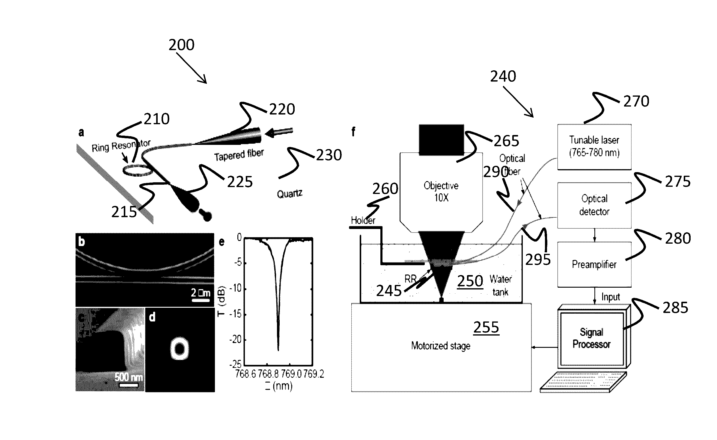
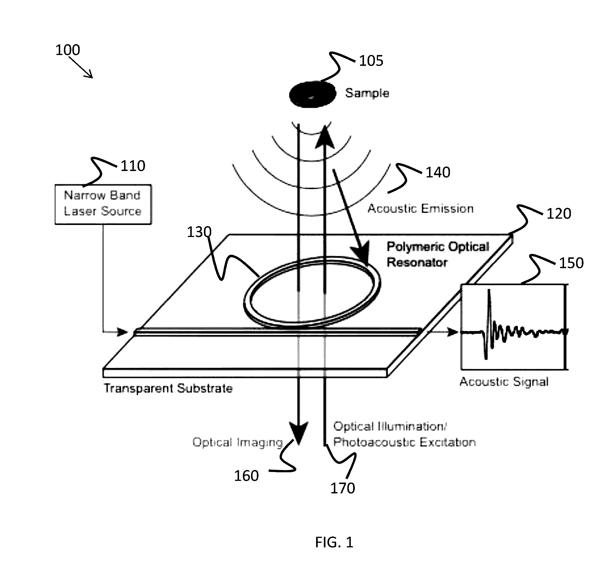
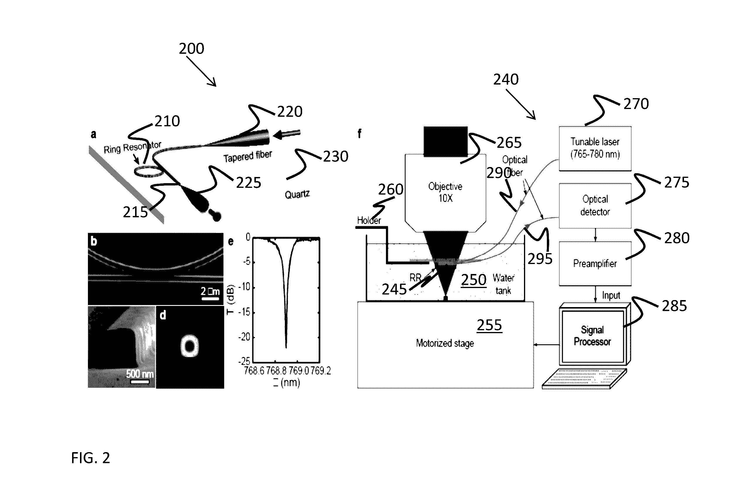
[0017]Certain examples provide an optically transparent, compliant (e.g., polymeric and / or other deformable material, etc.) photonic resonator which enables low-noise, wide-band detection of ultrasonic signals. Fabricating the polymeric resonator on a thin transparent substrate allows the transducer to be directly compatible with a conventional optical microscope or other optical imaging system for simultaneous optical and acoustic imaging. Using state-of-the-art nano-fabrication technique(s), an optical-based ultrasonic transducer can be fabricated at low cost. In addition, by utilizing coupled modes among multiple resonators, it is possible to reduce or eliminate a need for an expensive narrow band laser source to provide a fully integrated transducer that includes both active and passive photonic components.

[0018]In photoacoustic (PA) imaging, non-ionizing laser pulses are delivered into biological tissue (as opposed to radio frequency pulses used in thermoacoustic imagin...


PUM

PropertyMeasurementUnit
total thicknessaaaaaaaaaa
frequency bandwidthaaaaaaaaaa
transparentaaaaaaaaaa

Abstract

Certain examples provide a transparent ultrasonic transducer including a transparent substrate and a transparent optical resonator positioned on the transparent substrate. The transparent optical resonator is to facilitate excitation of a biological sample and to receive acoustic emission from the biological sample triggered by the excitation, for example.Certain examples provide a ring resonator ultrasonic detector including a microscope cover slide. The microscope cover sheet includes a substrate and a ring optical resonator positioned on the substrate. The example ring optical resonator is to facilitate illumination of a biological sample and to receive acoustic emission from the biological sample in response to the illumination.

Description

CROSS-REFERENCE TO RELATED APPLICATIONS[0001]The present application claims priority to U.S. Provisional Application No. 61 / 832,508, filed on Jun. 7, 2013, which is herein incorporated by reference in its entirety.STATEMENT REGARDING FEDERALLY SPONSORED RESEARCH OR DEVELOPMENT[0002]This invention was made with government support under RC4EY022883, RC4 EY021357, and R01 EY019951 awarded by the National Institutes of Health and CBET1055379, CBET1066776, and CMMI0955195 awarded by the National Science Foundation. The government has certain rights in the invention.FIELD OF THE DISCLOSURE[0003]The presently described technology generally relates to microscopy and, more specifically, to a transparent transducer to facilitate joint optical and / or acoustic imaging.BACKGROUND[0004]Photoacoustic imaging is a hybrid biomedical imaging modality developed based on a photoacoustic effect. The photoacoustic effect is a formation of sound waves following light absorption in a sample. In photoacoust...

Claims


Application Information

Patent Timeline
Patent Type & Authority Patents(United States)
IPC IPC(8): G01N29/06G01N29/24G01N29/14G01N29/34G01N21/17G02B6/12G02B6/122G02B21/00
CPCG01N29/0681G01N21/1702G01N29/14G01N29/2418G01N29/34G01N2291/02466G02B6/12007G02B6/1221G02B21/0004
Inventor ZHANG, HAO F.SUN, CHENG
Owner NORTHWESTERN UNIV
Why Eureka
Try Eureka