System for modular hip resurfacing

a hip resurfacing and modular technology, applied in the field of hip resurfacing arthroplasty, can solve the problems of femoral neck fracture, no additional fixation options for implants, and amstutz, bhr, bmhr systems do not allow for modular attachments, so as to simplify the process of performing osteotomy, reduce the risk of femoral neck notching, and facilitate the precise drilling of outer holes.

Active Publication Date: 2017-01-10
REVORTHO
View PDF33 Cites 1 Cited by
  • Summary
  • Abstract
  • Description
  • Claims
  • Application Information

AI Technical Summary

Benefits of technology

[0009]The modular hip resurfacing system according to an example embodiment of the present invention preserves a substantial collar of cortical bone, above the cartilage border, articular rim of the femoral head, and uses it for further implant support, as a periphery of the implant is partially mated to this strong, dense bone. Further, the modular hip resurfacing implant according to the present invention has threading at the base of its stem for modular attachments. This allows for the addition of a central screw, which can be used in combination with a femoral plate to significantly increase construct strength, when required.
[0010]Another benefit of the modular hip resurfacing implant according to an example embodiment of the present invention is additional threaded holes along the undersurface of the upper cap portion. These additional threaded holes provide for a wide range of fixation options, which can be used to further increase construct strength in the setting of localized bone deficiencies. Therefore, local cancellous bone deficiencies can be addressed in an individualized manner, depending on where the deficient cancellous bone is situated. The additional threaded holes on the undersurface of the upper cap portion of the modular hip resurfacing implant of the present invention greatly expand upon the fixation options available for the surgeon to address underlying bone deficiencies, and allow the use of additional screws and pegs for added fixation. In turn, these modular fixation options allow scalability for increasing implant strength, and provide durability and rotational stability during the lifecycle of the implant.
[0011]With respect to the tools used to perform hip resurfacing arthroplasty, there is a need for an alignment guide that ensures centralization of the guide pin within the femoral head, while also allowing for placement of the guide pin parallel to the femoral neck axis, as needed. There is also a need for an alignment guide that minimizes surgical access and exposure, and provides increased freedom for rotational adjustment. Further, there is a need for an alignment guide that does not involve manipulation of multiple adjustment joints for alternation of its orientation.

Problems solved by technology

Hip joint disease is a common problem affecting large populations with multiple etiologies including osteoarthritis, avascular necrosis, post-traumatic arthritis and other hip joint pathologies.
This is a significant disadvantage of these implants as they do not gain additional peripheral stability from the strong and dense cortical bone of the femoral head.
This endangers the femoral neck as it may be notched during bone preparations from contact with the cylindrical reamer, which may then lead to the devastating complication of femoral neck fracture during subsequent load bearing.
Additionally, the Amstutz, BHR, and BMHR systems do not allow for additional threaded modular attachments for increasing fixation of the implant to the underlying bone.
There are no additional fixation options for these implants in areas of poor bone quality.
This is a another significant limitation as the strength of cancellous bone can be highly variable depending on local hip conditions including avascular necrosis, localized bone cysts and osteolysis.
Soft cancellous bone can be encountered during surgery, but implant strength cannot be further increased with supplemental fixation.
However, this approach may remove healthy bone as a significant resection of femoral head bone is required during bone preparation for placement of the implant.
The Amstutz, BHR and BMHR designs also lack additional modular options for adding fixation.
Thus, the Amstutz, BHR and BMHR hip resurfacing systems have limited flexibility to address bone deficiency.

Method used


Image

  • System for modular hip resurfacing
  • System for modular hip resurfacing
  • System for modular hip resurfacing

Examples


Embodiment Construction

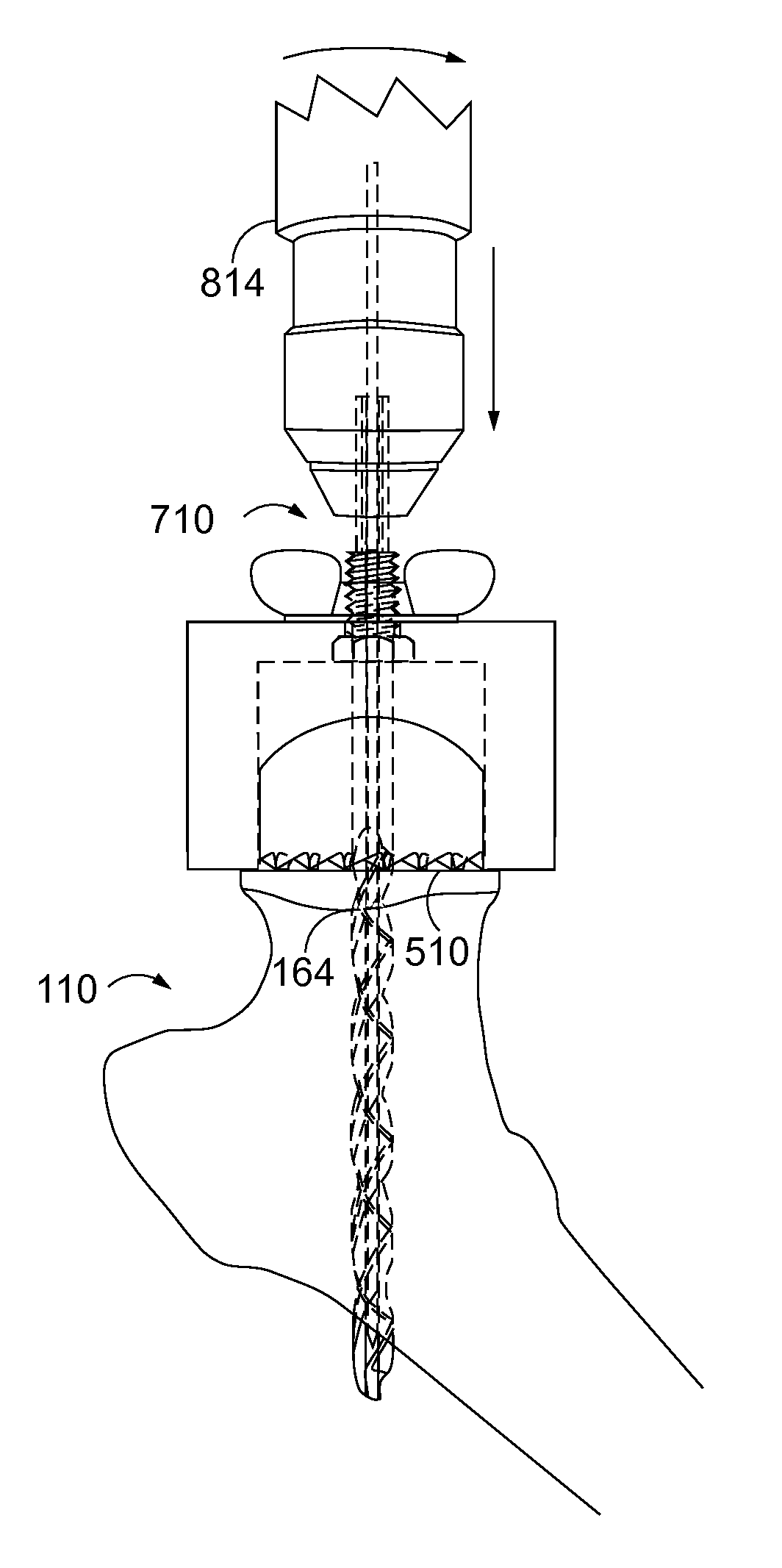
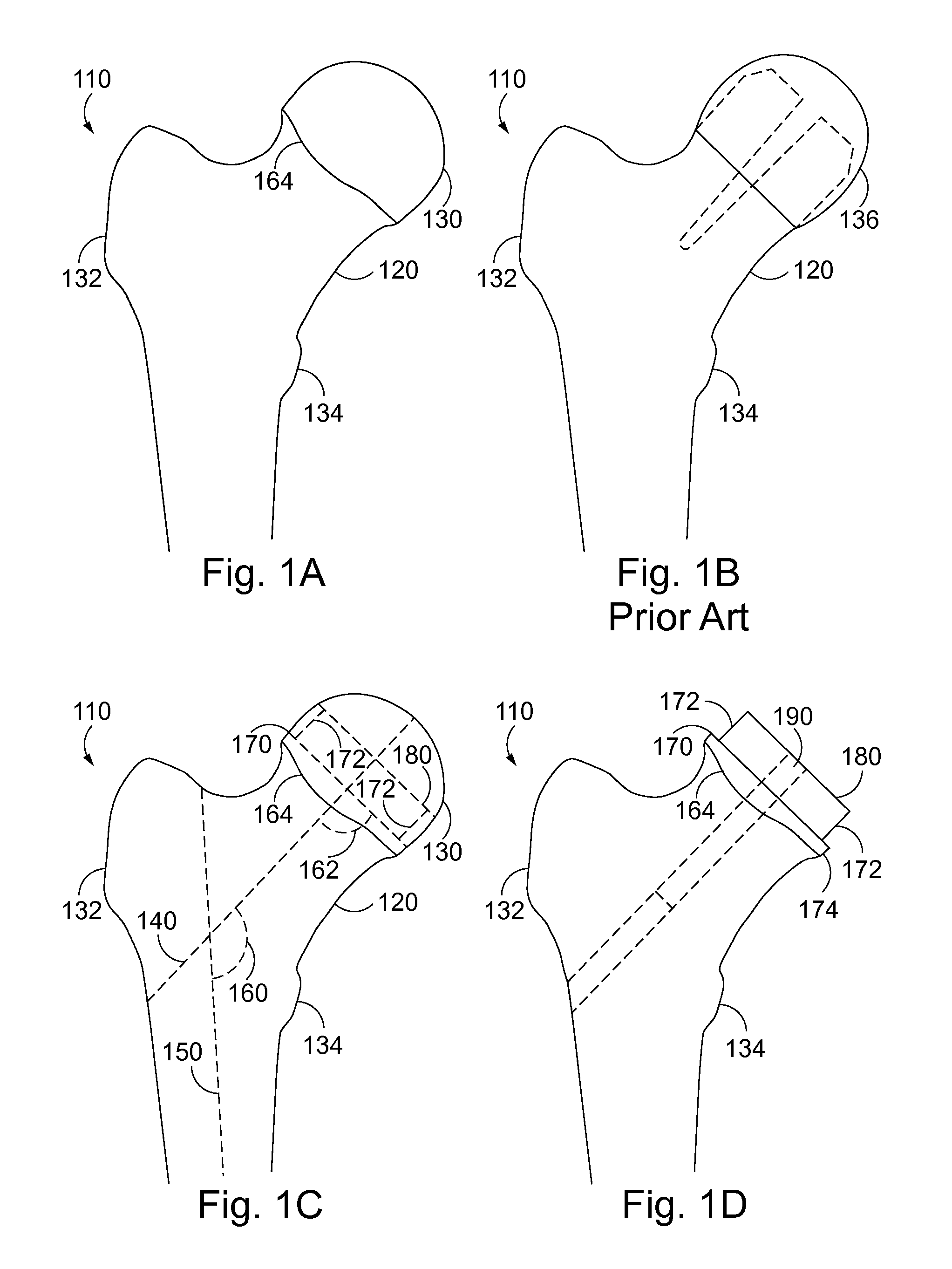
[0203]FIG. 1A is a front view from anterior of a human proximal femur 110 including femoral neck 120, femoral head 130, greater trochanter 132, lesser trochanter 134 and cartilage border, articular rim 164. FIG. 1B is a front view illustrating a proximal femur following bone cuts and implantation of a hip resurfacing femoral implant 136, according to previous devices such as the Birmingham Hip Resurfacing implant. The dashed line in FIG. 1B illustrates the required bone cuts following cylindrical reaming and osteotomies, for hip resurfacing femoral implants according to previous devices. Such a hip resurfacing femoral implant, as illustrated, has a solid stem without internal threading. Bone preparations for implantation of this hip resurfacing implant require cylindrical reaming of the femoral head past the cartilage edge, articular rim 164. As is typical with this implant, the outer, cortical, strongest bone of the femoral head is completely removed. The hip upper aspect of the hi...


PUM


Abstract

A scalable modular hip resurfacing arthroplasty system includes (1) an alignment guide for precise guide pin insertion, (2) a modular cannulated cylindrical reamer assembly for accurate femoral head cylindrical reaming and central bone channel drilling, (3) a saw guide for an accurate femoral head osteotomy, (4) a soft tissue protector with a stepped design to shield and retract tissues, (5) a hip retractor that seats onto a prepared femur, (6) an outer hole drill guide aiding drilling of peripheral holes, and (7) a femoral resurfacing implant with a cap portion and central stem adapted for multiple modular attachments including plates. A method for preparing the proximal femur for hip resurfacing with novel stepped cylindrical femoral head osteotomy and central bone channel drilling, leaving an intact collar of cortical bone above the femoral head articular rim.

Description

CROSS-REFERENCE TO RELATED APPLICATIONS[0001]The present application claims the benefit of U.S. Provisional Patent Application Ser. No. 61 / 815,255, filed Apr. 23, 2013 and U.S. Provisional Patent Application Ser. No. 61 / 841,892, filed Jul. 1, 2013 by the present inventors, the entire contents of each of which is incorporated herein by reference thereto.FIELD OF THE INVENTION[0002]The present invention relates to hip resurfacing arthroplasty.BACKGROUND INFORMATION[0003]Hip joint disease is a common problem affecting large populations with multiple etiologies including osteoarthritis, avascular necrosis, post-traumatic arthritis and other hip joint pathologies. Over the course of the past century, many surgical techniques have been advocated in attempts to both provide pain relief and improve hip joint mechanics and patient function. Multiple techniques have been proposed and widely utilized over the years. Early techniques of joint replacement replaced the entire femoral head with a ...

Claims


Application Information

Patent Timeline
Patent Type & Authority Patents(United States)
IPC IPC(8): A61F2/36A61B17/16A61B17/15A61F2/46A61B17/17A61B17/56A61B17/00A61B17/74A61F2/30
CPCA61F2/3603A61B17/15A61B17/1668A61B17/175A61B17/1721A61F2002/30878A61B17/1697A61B17/1753A61B17/746A61B2017/0046A61F2002/30299A61F2002/30405A61F2002/30433
Inventor KLINGER, CRAIG ERICTORO ARBELAEZ, JOSE BERNARDO
Owner REVORTHO
Why Eureka
Try Eureka