
Co-culture bioreactor system

a bioreactor and coculture technology, applied in the field of coculture bioreactor systems, can solve the problems of difficult in vitro culture of in vitro viable three-dimensional cellular constructs that mimic natural tissue, complicated in vivo system must be accurately modelled, and limit the means for better understanding biochemical communication, so as to prevent or minimize cell attachment

Active Publication Date: 2017-02-21
KIYATEC
View PDF13 Cites 6 Cited by
  • Summary
  • Abstract
  • Description
  • Claims
  • Application Information

AI Technical Summary

Benefits of technology

[0008]In a further aspect, the bioreactor systems of the invention can comprise a cellular anchorage in one or both of the respective culture chambers. Suitable cellular anchorage can be formed of multiple discrete scaffolds or single continuous scaffolds. Multiple discrete scaffolds can be maintained within a culture chamber through utilization of a retaining mesh that can hold the scaffolding materials within the chamber and prevent the loss of the scaffolding materials through the outlet of the culture chamber.
[0009]In one aspect, a cellular anchorage can be maintained at a predetermined distance from the membrane that separates the chambers. In one aspect, this predetermined distance can be selected to effect prevention or minimization of attachment of cells to the membrane and can act to maintain the physical isolation of different cell types within their respective culture chambers.

Problems solved by technology

The ability to culture in vitro viable three-dimensional cellular constructs that mimic natural tissue has proven very challenging.
One of the most difficult of the many problems faced by researchers is that there are multiple dynamic biochemical interactions that take place between and among cells in vivo, many of which have yet to be fully understood, and yet the complicated in vivo system must be accurately modeled if successful development of engineered tissues in vitro is to be accomplished.
Many existing co-culture systems are simple well plate designs that are static in nature and do not allow for manipulation of the local environment beyond the gross chemical inputs to the system.
However, known dynamic systems, similar to the static systems, often provide only a single source of nutrients / growth stimulants / etc. to all of the cell types held in the system.
Moreover, the different cell types that are co-cultured in both static and dynamic systems are usually maintained in actual physical contact with one another, preventing the development of an isolated cell population, and also limiting means for better understanding the biochemical communications between the cell types during growth and development.

Method used


Image

  • Co-culture bioreactor system
  • Co-culture bioreactor system
  • Co-culture bioreactor system

Examples


example 1

[0103]Cell Culture: A 3T3 mouse fibroblast cell line (available from ATCC, Manassas, Va.) was used in three studies (numbered 1-3 below) to examine cell viability when subjected to perfusion fluid flow in a system. A fourth study (Study 4) used a D1 cell line (ATCC) of adult mouse bone marrow stromal cells and incorporated hydrostatic compression in addition to the perfusion flow. The D1 cell line was selected due to its demonstrated multi-potent potential including favorable osteogenic properties.

[0104]Anchorage Fabrication: Multiple discrete poly-L-Iactide (PLL) hollow beads with an average diameter of 0.8 mm served as the discrete tissue engineering scaffolds for all studies. Briefly, scaffold fabrication was completed using solvent emulsion techniques, beginning with an 8% (m / v) solution of Purasorb polylactide pellets (Cargill, Minneapolis, Minn.) and dichloromethane (Mallinckrodt Baker, Phillipsburg, N.J.). A quantity of 5 ml of PLL solution was dispensed, using a 20 cc glass ...

example 2

[0113]Dynamic bioreactor systems were utilized to examine the influence of multiple mechanical stimuli on the differentiation traits of adult mesenchymal stem cells in addition to a variety of other cell types. The bioreactor was designed to model the in vivo conditions through available system conditions including hydrostatic loading. Perfusion of medium through the system was also adjusted to provide physiological levels of fluid shear stress across the cells.

[0114]Bioreactor systems such as that illustrated in FIG. 5 were prepared. Each 0.2 mL volume culture chamber was loaded with 45 mg PolyGraft™ granular material. A silicone diaphragm / gasket and four clamping socket screws were used to provide leak-free assembly of the culture chamber adjacent a pressure module.

[0115]All systems utilized a D1 cell line grown in quantity using standard cell culture flasks (Corning). The initial cell culture medium consisted of DMEM (ATCC) supplemented with 10% FBS and 1% antibiotic / antimycotic....

example 3

Novel 3D Cell Culture System

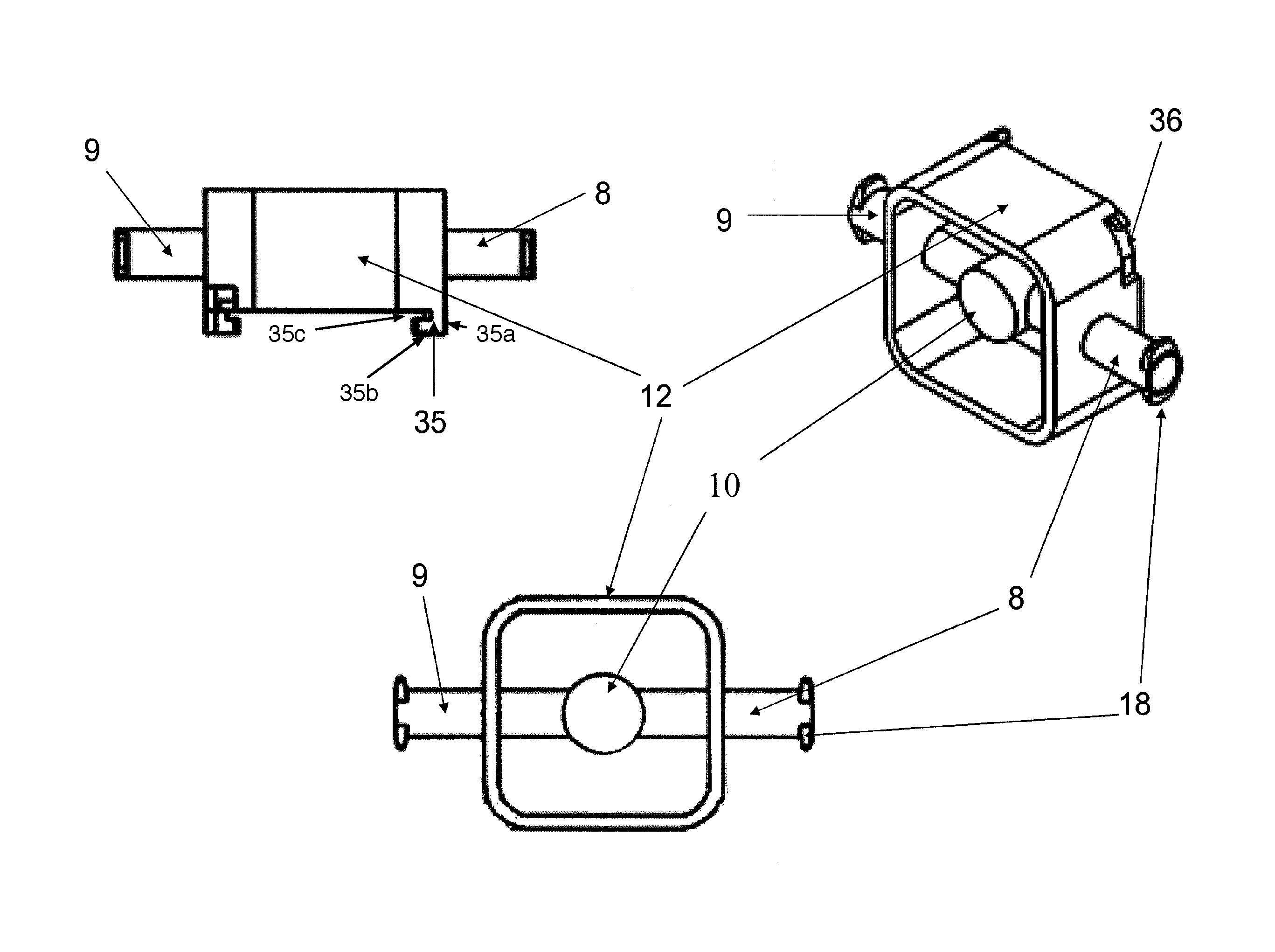
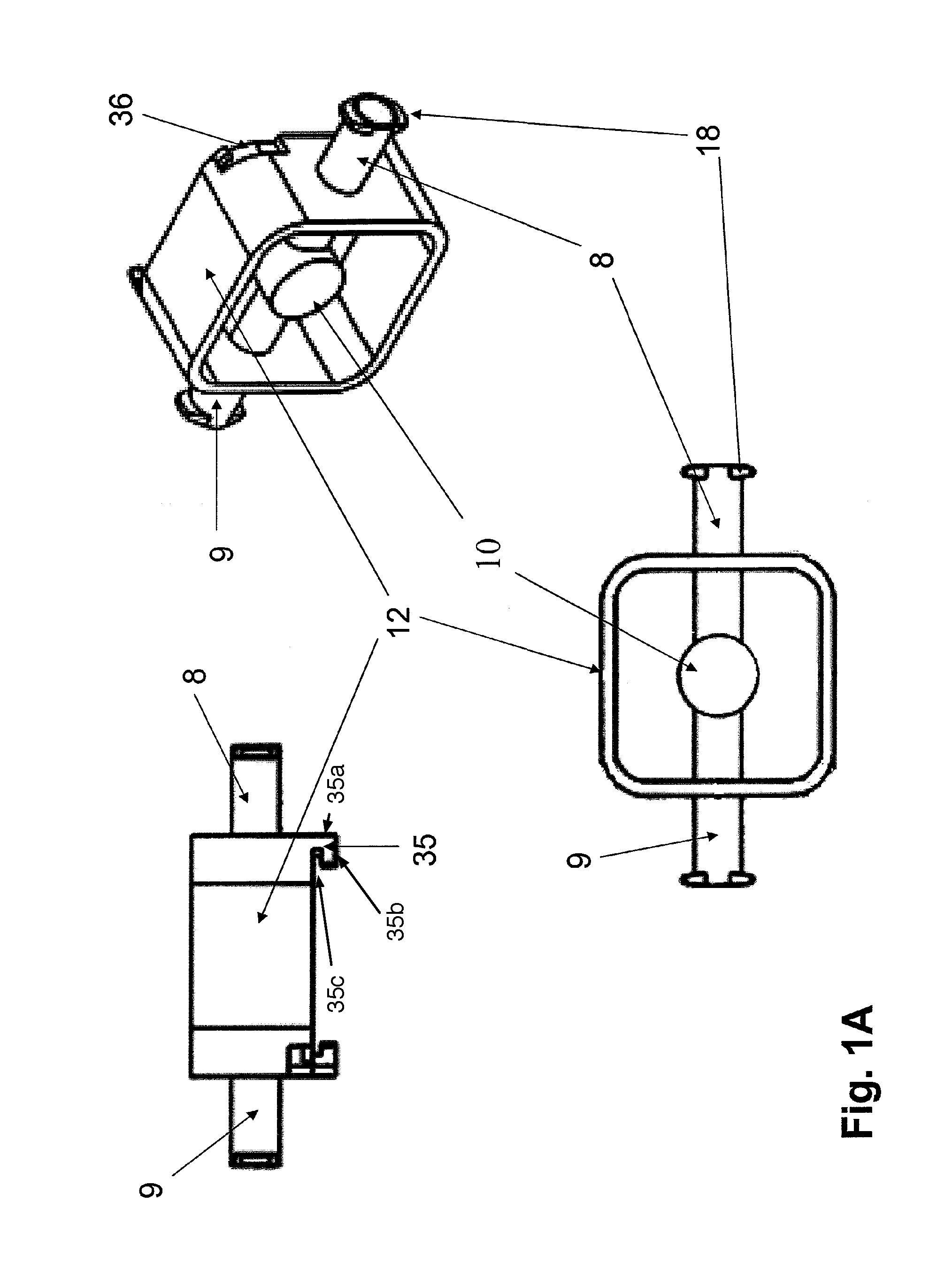
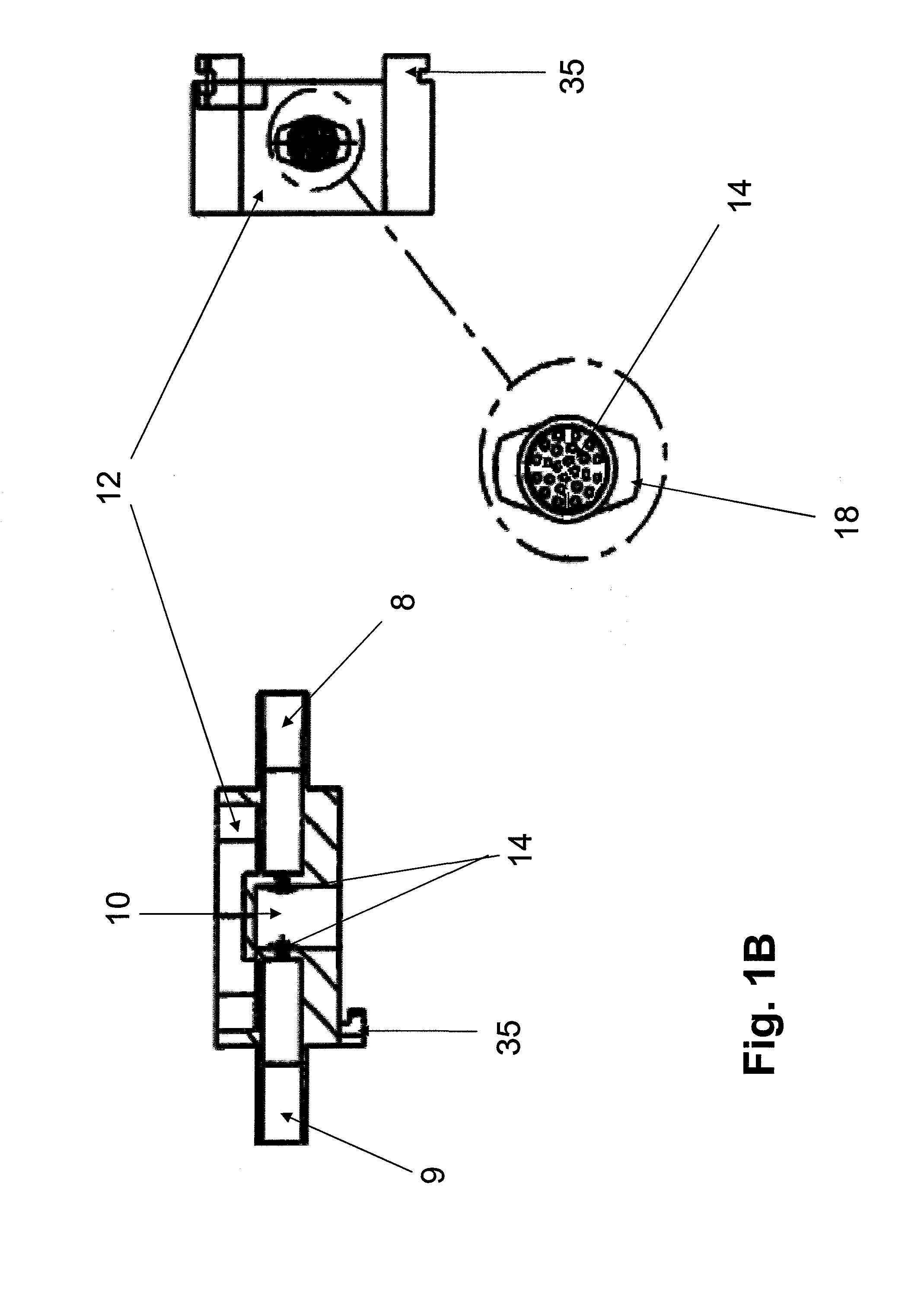
[0127]The use of injection-molded culture chambers (FIG. 18) allows the researcher to load the desired 3D scaffold material (FIG. 18A) of interest into two opposing culture chambers. The culture chambers can accommodate a variety of scaffold configurations including discrete beads, continuous porous constructs (e.g., sponge-like), and hydrogels, all retained by an integrated screen (FIG. 18B) molded directly into the fluid ports.

[0128]Cells can be loaded in the scaffold material prior to plasticware assembly or seeded post-assembly via manual syringe perfusion through the culture chamber and scaffold. The placement of a solid gasket (FIG. 18C) between the opposing culture chambers allows for two independent samples (n=2) within each plasticware assembly. Each chamber receives an independent perfusion (FIG. 18D) of culture medium that can accommodate unique chemical or mechanical stimulus for multiple experimental treatments. Integrated inlet and outlet po...


PUM

PropertyMeasurementUnit
pore sizeaaaaaaaaaa
pore sizeaaaaaaaaaa
diameteraaaaaaaaaa

Abstract

Disclosed herein are bioreactor systems and methods of utilizing said systems.

Description

BACKGROUND OF THE INVENTION[0001]The ability to culture in vitro viable three-dimensional cellular constructs that mimic natural tissue has proven very challenging. One of the most difficult of the many problems faced by researchers is that there are multiple dynamic biochemical interactions that take place between and among cells in vivo, many of which have yet to be fully understood, and yet the complicated in vivo system must be accurately modeled if successful development of engineered tissues in vitro is to be accomplished. The ideal in vitro system should accurately model the mechanical environment as well as the essential cellular interactions found during in vivo development while providing purity of the desired product construct so as to enable utilization of the product, for instance as transplantable tissue. For example, it is commonly desired that the product cells be isolated and free from extraneous cells of other phenotypes, and in particular those previously shown to...

Claims


Application Information

Patent Timeline
Patent Type & Authority Patents(United States)
IPC IPC(8): C12M3/00C12M1/00G01N33/50C12M1/42
CPCG01N33/5029C12M23/34C12M23/44C12M29/04C12M35/08G01N33/5011C12N5/0693C12N2500/00C12N2502/00C12N2503/00C12N2503/02G01N33/5091
Inventor GEVAERT, MATTHEW R.ORR, DAVID E.
Owner KIYATEC
Learn More