Storage time control

a technology of storage time and control, applied in the direction of process and machine control, pulse technique, instruments, etc., can solve the problems of increased power waste, device damage, energy loss, etc., and achieve the effect of fast turn-on of power switching devices and high first amplitud

Inactive Publication Date: 2017-04-11
POWER INTEGRATIONS INC
View PDF21 Cites 1 Cited by
  • Summary
  • Abstract
  • Description
  • Claims
  • Application Information

AI Technical Summary

Benefits of technology

[0019]In broad terms, delivering a large charge to the control terminal reduces the voltage across the switching device in the on state (if the charge delivered is too small the device can be damaged by dissipating too much power). However energy is lost as the voltage across the device increases when the device is turned off, and the greater the charge to extract, the greater the wasted power. Thus embodiments of the method select a (fixed) target time to balance an increased input charge amount for a low on-state voltage drop across conduction terminals of the switching device with the power loss during turn-off. In principle the target time may be varied with the input supply voltage—if this voltage is low the power loss is more sensitive to the voltage across the switching device when switched on; if the supply voltage is high the power loss is less sensitive to the voltage across the switching device when on, but the energy loss during turn-off may be increased. Thus the target time may be varied (for example, by defining values in a lookup table), according to the supply voltage to optimise for overall efficiency (low power loss). This may be generalised to vary the target time in response to other operating conditions, for example the delivered power or operating (switching) frequency of the SMPC, an on-time of said switching device, and / or a temperature of said SMPC or of the switching device. Optionally a limit (in particular an upper limit) may be provided for the target time to reduce the risk of an overly long target time interfering with a higher level power delivery control loop for the SMPC (which, in embodiments, controls the total turn-on time), or too short a target time which may risk premature turn-off (causing high power loss and risking damage to the switching device).
[0058]In an embodiment, peak detection may allow power efficient use of a power switching device such as a BJT, by allowing variation of an on time comprising a variable turn off delay time to be monitored and preferably used for subsequent control of the device, and / or may allow rapid fault detection. Furthermore, circuitry may be minimised by re-use of peak detection circuitry for example used to sense an output voltage in an embodiment. Thus, cost and / or space efficiencies may be obtained.

Problems solved by technology

In broad terms, delivering a large charge to the control terminal reduces the voltage across the switching device in the on state (if the charge delivered is too small the device can be damaged by dissipating too much power).
However energy is lost as the voltage across the device increases when the device is turned off, and the greater the charge to extract, the greater the wasted power.

Method used


Image

  • Storage time control
  • Storage time control
  • Storage time control

Examples


Embodiment Construction

[0107]Embodiments provide a number of improvements to bipolar transistor drive for low cost SMPCs. For example, a wide range of transistors may be driven optimally by regulating their turn-off delay time, generally comprising a charge storage time. This is performed in an embodiment using a reliable, low cost approach that requires minimal, preferably no, additional parts for a primary side-sensing flyback converter.

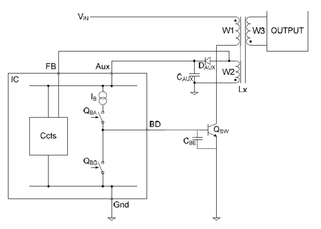
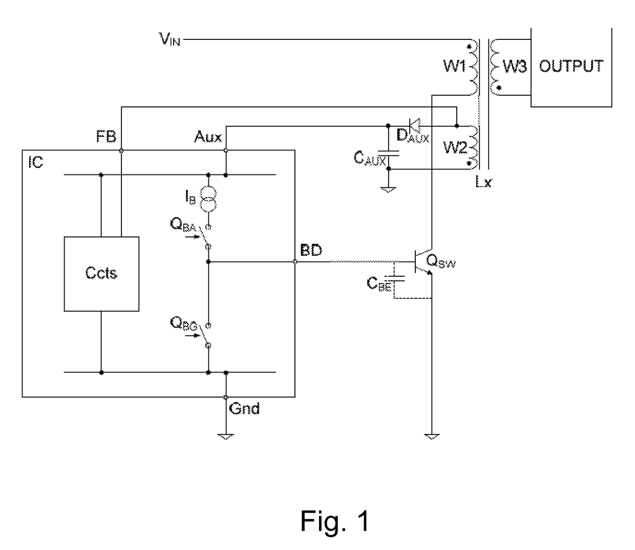
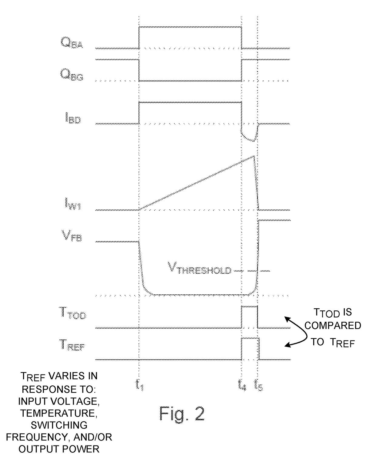
[0108]One embodiment is shown in FIG. 1, with example waveforms in FIG. 2. The offline switched mode power converter may be of any type, for example flyback, boost or forward converter, and is shown here as a single-ended flyback design. The inductive component Lx illustrated in FIG. 1 is a coupled inductor having windings W1 (input, primary winding), W3 (output, secondary winding) and further winding W2 (preferably a sensing signal source in the form of, e.g., an auxiliary or sense winding). However alternative inductive components Lx may be employed, depending on the c...


PUM


Abstract

A switch mode power converter (SMPC) includes a switching control system to control the turn off time delay of a switching device. The SMPC also has an inductive component including an input winding to receive power from an input and a switching device to conduct input winding current. The switching control system applies turn on and turn off signals to the switching device. The turn off signal initiates turning off of the switching device and a sensing signal from a further winding inductively coupled to the input winding is detected to indicate an end of a turn off time delay or duration. The turn on signal for a subsequent switching cycle of the SMPC device is controlled to regulate the turn off delay time.

Description

RELATED APPLICATIONS[0001]This application claims priority under 35 U.S.C. 119(e) to U.S. Provisional Application No. 61 / 829,404, filed May 31, 2013; which application is incorporated herein by reference in its entirety.FIELD OF THE INVENTION[0002]This invention generally relates to methods of indicating an on time of a power switching device of a switch mode power converter (SMPC) and switching control systems for controlling an on time of a power switching device of an SMPC, and more particularly to an SMPC.BACKGROUND TO THE INVENTION[0003]Bipolar transistors, conventionally bipolar junction transistors (BJTs) but also including insulated gate bipolar transistors (IGBTs), have been used in switched mode power converters (SMPCs) for many years. BJTs in particular are relatively inexpensive and rugged devices, with low on-state resistance and high power density.[0004]The use of a low cost bipolar junction transistor (BJT) as the primary switch in an offline power converter is desira...

Claims


Application Information

Patent Timeline
Patent Type & Authority Patents(United States)
IPC IPC(8): H02M3/335H02M3/156H02M1/00H03K17/042
CPCH02M3/33507H02M3/156H02M2001/0009H02M2001/0054H03K17/04213Y02B70/1491H02M1/0009H02M1/0054Y02B70/10H02M1/08
Inventor RYAN, PAULPIPER, JOHAN
Owner POWER INTEGRATIONS INC
Why Eureka
Try Eureka