
Abrasive sawing wire, production method thereof and use of same

a technology of abrasive sawing wire and production method, which is applied in the field of sawing, can solve the problems of reducing affecting partly eroded binding layer to expose the abrasive particles, etc., and achieves the effect of improving the hardness of ni/co alloy binder, improving abrasion resistance, and improving hardness

Inactive Publication Date: 2017-04-18
COMMISSARIAT A LENERGIE ATOMIQUE ET AUX ENERGIES ALTERNATIVES +1
View PDF21 Cites 0 Cited by
  • Summary
  • Abstract
  • Description
  • Claims
  • Application Information

AI Technical Summary

Benefits of technology

[0018]Further, the binder protects the core of the wire from a premature wearing on use thereof. Its specific composition enables to improve the resistance to mechanical deformation, but also the resistance to abrasion during cutting operations, and this, while minimizing abrasive particle losses.
[0022]Indeed, the Ni / Co alloy having a cobalt content in the range from 20 to 85% by mass provides a better hold of the particles on the core than prior art resin binders. It has properties of hardness and resistance to abrasion enabling to more efficiently maintain the particles in place, even on use of the wire during cutting operations.
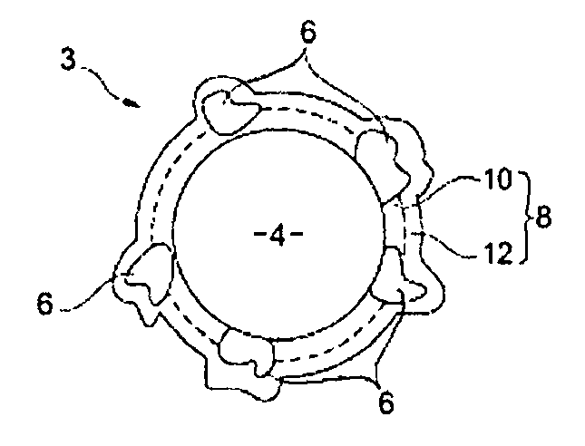
[0031]According to a specific embodiment, the abrasive wire comprises a steel core and an external coating comprising a binder and abrasive particles. The binder is formed, in this specific case, of two binder layers may of a nickel / cobalt alloy, having a cobalt content in the range from 20% to 85% by mass with respect to the mass of the Ni / Co alloy (independently from one layer to the other). The second binder layer which covers the first binder layer adjacent to the steel core is made of a Ni / Co alloy containing more cobalt than the first binder layer. Thus, the external binder layer (second layer) has better abrasion resistance properties due to the high cobalt percentage. Further, the first layer has better hardness properties than the binder alloy of the second layer due to its adapted composition.
[0032]According to another specific embodiment, the hardness of the Ni / Co alloy binder may be improved by introduction of sulfur. This may in particular be implemented according to the method described hereafter, by introduction of sodium saccharin (C7H4NO3S, Na, 2H2O) into the electrolyte bath enabling to form the binder layer.

Problems solved by technology

Indeed, on first use of the wire, the binder is partly eroded to expose the abrasive particles.
However, it may wear according to the two following mechanisms:by mechanical deformation: on sawing of a material, the abrasive particles are alternately pushed forward and backward and along the main direction of the wire.
Due to the sawing movements, the fragments of material erode the binder, with, as a consequence, a progressive decrease of its thickness.
At the end of the cutting, the binder is no longer thick enough to efficiently retain the abrasive particles at the surface of the wire.
The abrasive particles detach, which progressively decreases the abrasive power of the wire and thus its ability to cut a material.
However, steel wires are sensitive to corrosion, in particular when there exists an electrolytic contact between the steel and a nobler metal, such as copper, nickel, or cobalt.
The wire is stretched (and its bonding metal layer may then crack) and it is sprayed with water.

Method used


Image

  • Abrasive sawing wire, production method thereof and use of same
  • Abrasive sawing wire, production method thereof and use of same

Examples


Embodiment Construction

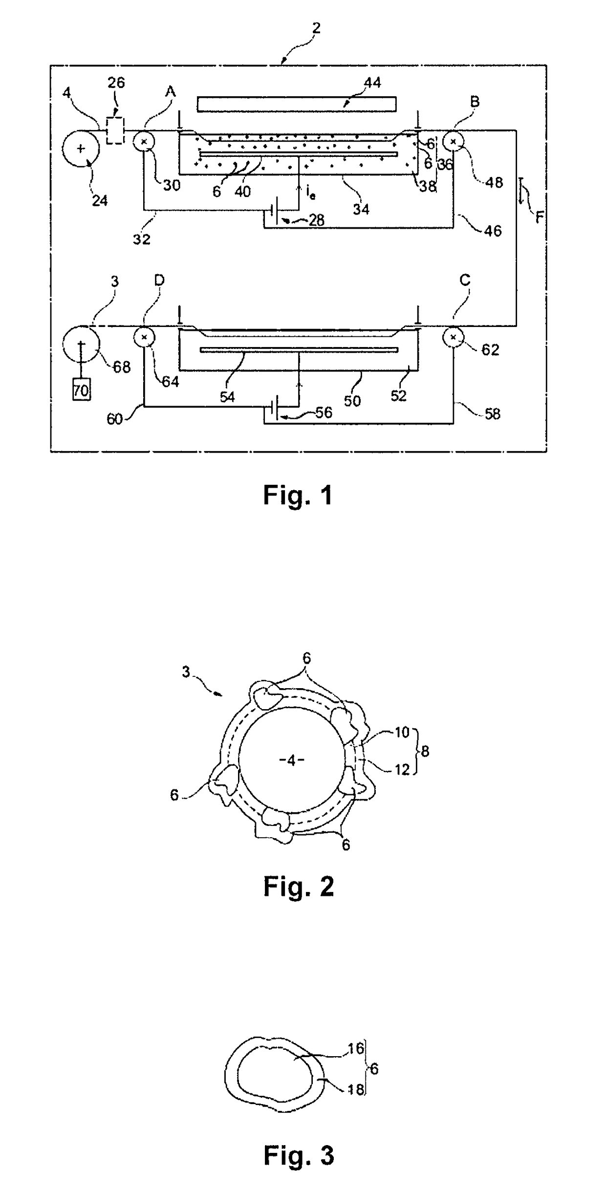
[0077]The device (2) illustrated in FIG. 1 enables to implement a specific embodiment of the electrodeposition method on a steel wire (4) to prepare the abrasive wire (3) according to the present invention.

[0078]The method especially comprises the steps of:[0079]unwinding a steel core (4) (steel wire) stored in the form of a coil (24), along the direction of arrow F;[0080]optionally, degreasing steel core (4) in an alkaline medium;[0081]optionally, pickling steel core (4) in an acid medium;[0082]optionally, passing steel core (4) through a magnetization device (26) which applies a magnetic field, having an intensity advantageously greater than 800 Nm. Core (4) is thus permanently magnetized;[0083]electrodepositing on the steel core a coating comprising a binder and abrasive particles, said binder being a nickel / cobalt alloy having a cobalt content in the range from 20% to 85% by mass relative to the mass of the Ni / Co alloy, by passing in a bath (B1) (36) of electrolyte (38) comprisi...


PUM

PropertyMeasurementUnit
forceaaaaaaaaaa
total diameteraaaaaaaaaa
diameteraaaaaaaaaa

Abstract

An abrasive wire including a steel core and an outer coating including a binder and abrasive particles, the binder being formed by at least one nickel-cobalt alloy layer having a cobalt content of between 20 wt.-% and 85 wt.-% in relation to the weight of the Ni / Co alloy.

Description

FIELD OF THE INVENTION[0001]The invention relates to an abrasive wire comprising a steel core and abrasive particles maintained on the core by means of a binder based on a Ni / Co alloy.[0002]The field of use of the present invention particularly concerns the sawing of materials such as silicon, sapphire, or silicon carbide.BACKGROUND OF THE INVENTION[0003]Generally, the cutting of hard materials such as silicon wafers may be performed by means of a wire (steel) having abrasive particles (diamond, for example) at its periphery.[0004]To solve possible wire breaks, prior art advocates the use of a steel wire having a high carbon content.[0005]Abrasive particles are bonded to the wire by means of a resin or metal binder layer. Such a binder maintains the particles at the surface of the wire to give abrasive properties thereto.[0006]Generally, and conversely to the binder, the particles are made of a material harder than the material to be cut.[0007]Indeed, on first use of the wire, the b...

Claims


Application Information

Patent Timeline
Patent Type & Authority Patents(United States)
IPC IPC(8): B28D5/00C25D15/00B28D5/04B24D11/00B24D18/00B23D65/00B23D61/18C25D7/06
CPCB23D61/185B23D65/00B24D11/00B24D18/0018B28D5/04C25D7/0607C25D15/00
Inventor LY, MICHELSANCHEZ, GERALDWEBER, XAVIER
Owner COMMISSARIAT A LENERGIE ATOMIQUE ET AUX ENERGIES ALTERNATIVES
Learn More