Electric vehicle shielded power cable connector

a technology for shielded power cables and electric vehicles, which is applied in vehicle connectors, couplings/cases, and vehicle connection connections, etc., can solve problems such as resistive heating, damage to adjacent parts, and reduce the efficiency of electric systems

Active Publication Date: 2017-05-02
HUBERSUHNER AG
View PDF15 Cites 8 Cited by
  • Summary
  • Abstract
  • Description
  • Claims
  • Application Information

AI Technical Summary

Benefits of technology

[0013]The shielded cable connector assembly can further comprise an adhesive sealer that covers the compression ring and the braided sheath at least in the area where the braided sheath is pinched, such that the cable and connector are mechanically fixed and a contact area between the braided sheath and the connector is protected from corrosion.
[0014]Preferably, the adhesive sealer penetrates the braided sheath between the core insulator and the outer insulator over a distance sufficient to prevent capillary flow of environmental media along the sheath through the cable.
[0018]In some embodiments, an adhesive provided in a least a portion of the interstitial areas where the flexible braided sheath layer is pressed between the interior surface of the frustoconical space of the connector body and the frustoconical outer surface of the tapered compression ring. In some embodiments, the adhesive comprises an epoxy resin. In some embodiments, the adhesive provides protection against galvanic corrosion of the connector assembly.
[0019]In some embodiments, an adhesive sealer is provided in at least a portion of the frustoconical space inside the connector body. In some embodiments, the adhesive sealer comprises a bonding filler, epoxy resin or silicon resin. In some embodiments, the adhesive sealer resists penetration of fluids and particles into the frustoconical space in the connector body. In some embodiments, the adhesive sealer provides protection against galvanic corrosion of the connector assembly. In some embodiments, the adhesive sealer increases the reliability of the connector assembly by eliminating electrical shorts caused by vibrational flexing and breakage of the flexible braided sheath.
[0023]In some embodiments, the connector body includes an exterior surface ridge around the perimeter at the connector body first end and the flexible boot includes an interior lip at the flexible boot first end, such that the interior lip and the exterior ridge engage to inhibit the flexible boot slipping off the connector body.

Problems solved by technology

Excessive electrical resistance in the connection will cause resistive heating.
Any electric power expended in the form of heat generation due to resistive heating will reduce the efficiency of the electric system, which must be avoided in an electric powered vehicle.
In addition, excessive heat generated in the connector can cause corrosion of conductors, melt insulators, deteriorate materials from which the connector is constructed, cause damage to adjacent parts and increase a risk of fire.
Gaps or inconsistencies in the outer conductor (braided sheath) at the connector will reduce the shielding capability of the connector.
Since electromagnetic interference can induce soft errors in a vehicle's electronic systems, poor protection against such interference in an electric or hybrid / electric vehicle could potentially damage the electronics and computer systems controlling the vehicle and affect the safe operation of the vehicle, putting passengers and others at risk of harm.
Many connectors manufactured by prior art methods (e.g., stamping) have seams that can cause gaps in RF shielding of the transmission path.
In addition, the internal surfaces of many connectors made by prior art methods provide inferior quality electrical contact to the braided sheath and a higher resistance electrical path to ground.
As a result, connectors of the prior art can produce excessive interference and provide inferior grounding.
In addition to electrical considerations, connectors used inside a vehicle will be subjected to vibrations and other mechanical stresses during vehicle operation.

Method used


Image

  • Electric vehicle shielded power cable connector
  • Electric vehicle shielded power cable connector
  • Electric vehicle shielded power cable connector

Examples


first embodiment

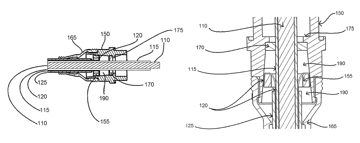
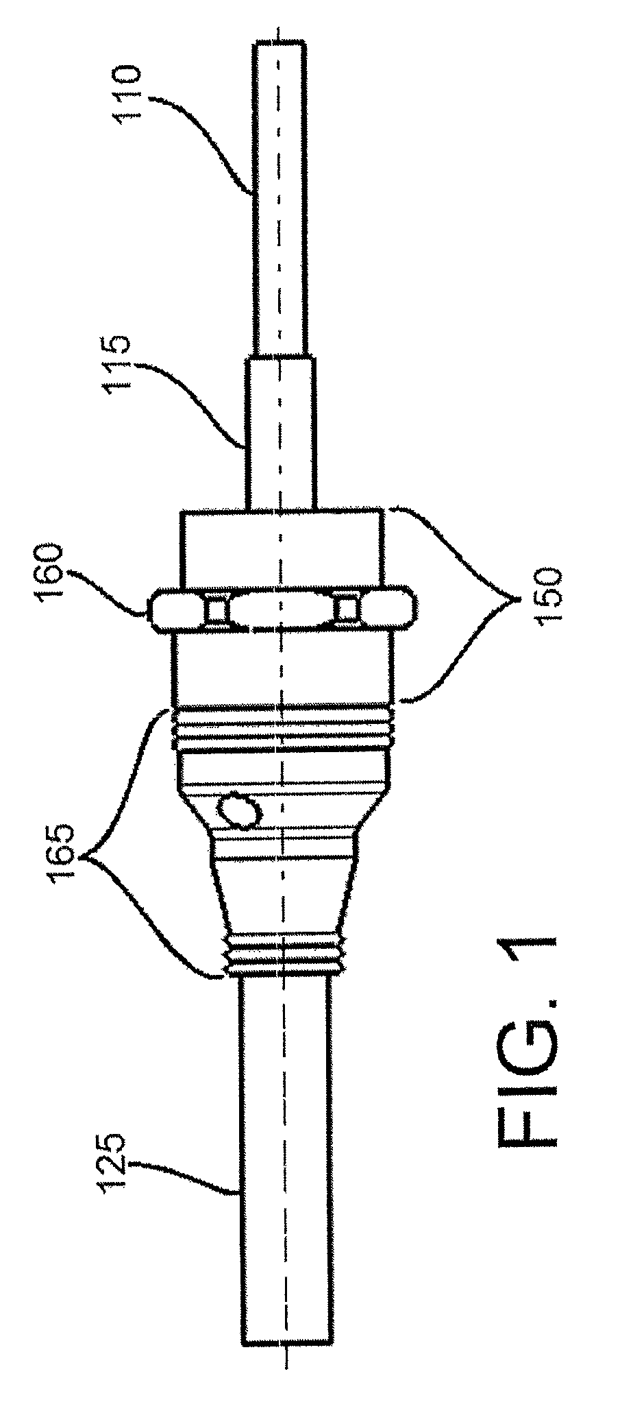
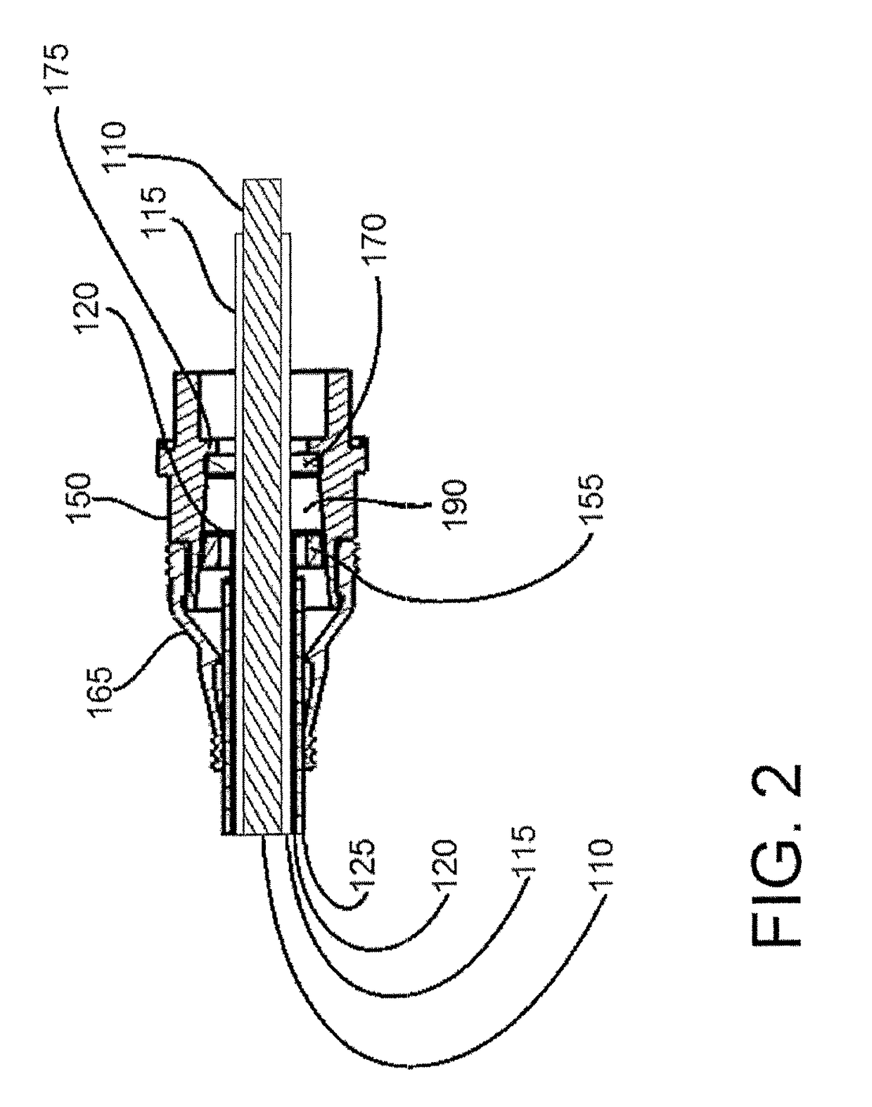
[0035]FIG. 1 illustrates a shielded cable having a connection end prepared for connection to a termination point and the connector of the present invention assembled therewith. Connector body 150 includes mounting feature 160 for mechanically attaching the connection end of the connector to a termination point. The connector in FIG. 1 further comprises flexible boot 165 positioned over a cable end of connector body 150.

[0036]Flexible boot 165 extends from the cable end of connector body 150 onto the shielded cable outer insulator 125. The flexible boot 165 includes constrictive ridges on both ends to provide an environmental seal to the external surfaces of the cable end of connector body 150 and the outer insulator 125. The exterior of flexible boot 165 tapers from a diameter large enough to snugly fit over the cable end of connector body 150 to a smaller diameter providing a seal around the outer insulator 125. Flexible boot 165 is optionally but preferably provided to prevent flu...

second embodiment

[0051]In an illustration of the present invention, FIG. 4 shows that an adhesive 200 may be provided where the flexible braided shield sheath 120 is compressed between the tapered compression ring 155 and the hollow interior surface of the connector body 150. This embodiment of the present invention increases the mechanical strength (i.e., ruggedizes) of the connector assembly created by the self-locking tapered surfaces of the connector body 150 and tapered compression ring 155. The adhesive 200 used in this embodiment may be an epoxy or other strong securing medium. In an exemplary embodiment, the adhesive 200 is capable of exposure to high heat when set and is of a low viscosity when applied such that there is capillary penetration to fill, partially or completely, the interstitial spaces between the braided shield wires of sheath 120 in the region where they are compressed. The adhesive 200 may be provided to some or all of the compressed area of sheath 120.

[0052]FIG. 5 provides...

embodiment 3

[0053]A benefit of the adhesive 200 applied to the braided sheath 120, in FIG. 4, is protection against galvanic corrosion due to the electrochemical potential between the dissimilar metals of the braided sheath and the connector body. With the addition of the adhesive 200, it can be seen that the critical junction between the cable shield 120 and the connector body is encapsulated in a protective resin in This prevents any corrosion that can be precipitated by the presence of dissimilar metals in contact with one another. In an embodiment that includes both the adhesive 200 of FIG. 4 and the adhesive sealer 310 of FIG. 5, the adhesive sealer 310 further protects the metals at the junction from harsh environmental conditions that would promote corrosion.

[0054]A further benefit that the sealing adhesive 310 provides is an improvement over prior art connectors in which shield wires harden from vibration, break free, and can then migrate to some point where a short circuit can occur. ...


PUM


Abstract

A connector assembly mechanically and electrically connects a shielded power cable, capable of conducting DC and multiple phase AC electric power, to drive motors and powered accessories of an electric vehicle. The connector assembly includes a shielded power cable, a connector body, a sealing ring, a tapered compression ring and a flexible rubber boot. The hollow frustoconical interior of the connector body and the frustoconical tapered compression ring, with the shield layer of the power cable compressed between them, form a self-locking taper that provides a strong mechanical connection. The sealing ring and the flexible rubber boot inhibit penetration of fluids and particles into the connector assembly. The addition of an adhesive to the compressed section strengthens the connection and reduces corrosion. Filling empty spaces inside the connector body with an adhesive sealer further prevents penetration by contaminants, reduces corrosion and strengthens the connector.

Description

CROSS-REFERENCE TO RELATED APPLICATIONS[0001]This application is a continuation-in-part of International Application No. PCT / US2014 / 047821 filed Jul. 23, 2014, and claims priority to U.S. Provisional Application Ser. No. 61 / 958,388, filed Jul. 26, 2013, the entireties of which are incorporated herein by reference.FIELD OF THE INVENTION[0002]This invention is directed generally to a connection device for a flexible power cable and, in particular, to a shielded cable connector assembly for electrically terminating, grounding, and mechanically securing a shielded cable. More specifically, the invention is directed to a device and method for providing very low electrical resistance grounding and secure mechanical connection between a termination point and a shielded power cable used to transmit power in an electric or hybrid-electric vehicle.BACKGROUND OF THE INVENTION[0003]As a result of the widespread development of electric powered and hybrid / electric powered vehicles, there is a nee...

Claims


Application Information

Patent Timeline
Patent Type & Authority Patents(United States)
IPC IPC(8): H01R13/6592H01R13/52H01R9/05
CPCH01R13/6592H01R13/5205H01R9/0524H01R2201/26
Inventor LOVELESS, RICHARD WHITCOMBWHITCOMB, RANDALL FOSTER
Owner HUBERSUHNER AG
Why Eureka
Try Eureka