Thermal plasma treatment method

a treatment method and plasma technology, applied in the field of plasma treatment method, can solve the problems of general inefficiency of the process itself, general inefficiency of the process, environmental protection, etc., and achieve the effects of preventing the cracking of heating elements, increasing the thickness and porosity of materials, and increasing the pore siz

Active Publication Date: 2017-05-09
MHI HEALTH DEVICES
View PDF6 Cites 5 Cited by
  • Summary
  • Abstract
  • Description
  • Claims
  • Application Information

AI Technical Summary

Benefits of technology

[0008]The present method uses electricity and just air (or any other gas) to produce a high temperature thermal plasma plume that contains ions, electrons, radiation and hot gas. This type of plasma is differentiated from plasma which is generated due to a mere electric potential. The First Ionization Energy of an element (atom) is utilized in this method. The First Ionization Energy is the energy needed to remove the outermost electron from a neutral atom in the gas phase. When recombination with an electron occurs for the ionized atom, tremendous heat is generated. Thus rapid heating of a surface / substrate is the result.
[0009]This method provides non-contact, continuous heating with accurate temperature control in compact versatile use designs. The method can provide normalizing, stress relieving, annealing, hardening, curing, deformation (bending or shaping), surface melting and coating. Processes may be completed while wire or cable is moving through the high temperature plasma environment. This type of heating provides the rapid high temperature heating necessary for melting and heat treating. Anticipated applications include, but are not limited to; stress relieving, annealing, hardening, curing, surface melting, surface coating, hard-facing, powder sintering, compacting to a substrate, creating high hardness surfaces, coating formation (rapid manufacturing of tungsten carbide-Co alloys with excellent bonding on any metal platform), powder processing, thin film treatment and processing, densification of materials (ceramics, powders, metals, etc.) and creating / treating highly wear / abrasion resistant surfaces. Radiant heat may also be applied concurrently with the application of, or immersion in, plasma. It has been found that this process can effectively bend, form and texture glass. Spent abrasive wheels can be reconditioned by the application of thermal plasma to grinding surfaces. Drill bits and other cutting tools may be treated with thermal plasma resulting in harder and longer lasting cutting surfaces. Old cutting tooling may be reconditioned by application of thermal plasma as well.
[0014]As shown in FIG. 6, the blower preferably has an insulating liner 38 adjacent the interior surfaces of shell 14 for preventing loss of heat from the interior of the blower. Insulating liner 38 can comprise any insulating material that is physically and chemically stable at the temperature at which the blower is to operate, such as alumina silica fibers, micro quartz fiber and the like.
[0018]Furthermore, it is contemplated that hot air could be drawn directly out of the gap as it is simultaneously drawn from the outlet end of the blower or compressor or gas bottle delivering the gas. Moreover, additional fans may be utilized to aid in drawing the air from the blower. It is also contemplated that fins or baffles be utilized within the gap to aid in increasing residence time and raising the temperature of the air output from the fan. In operation, the blower, fan or compressor forces air (or other gas, if desired) into the inlet. When the air reaches the first material, it travels from the inlet side, through the pores, and out the outlet side. As noted above, the pores preferably provide a plurality of passageways through which the air may travel. It is even more preferred that the passageways have several turns and twists so that the air travels a “tortuous” path, as is known in the art. As also noted above, the pores within the material are preferably interconnected so that each pore is connected to a plurality of passageways extending from the inlet side to the inner side. The first material has a preferred porosity of 10 pores per inch, each pore having a diameter of about 0.01 inches.
[0019]The tortuous path provided by the pores serves at least two functions. First, as air travels the tortuous path, it absorbs the heat retained by the first material and received from the heating element. This preheating of the air helps to prevent the heating elements from cracking, as metallic elements have been known to do when they come in contact with air that is too cool relative to the temperature of the element. The amount of preheating that occurs depends upon the thickness of the material, the porosity of the material, and the size of the pores. The greater the thickness and porosity of the material, the more tortuous will be the path. The larger the pore size, the less tortuous the path.
[0020]The second function of the tortuous path is to help to prevent air from escaping the blower in the opposite direction of the intended flow. Thus, although air that becomes heated will have a tendency to rise from the inner side to the inlet side when the blower is used in the vertical position, the air will have difficulty doing so due to the complex and turbulent flow experienced within the gap upon exiting the material.

Problems solved by technology

These long dwell times lead to oxidation and discoloration problems associated with work pieces as well as general inefficiency of the process itself.
Other heat treatment methods which employ combustion or open flames are environmentally unfriendly and are generally hazardous and energy inefficient.
Presently, the energy inefficiency of many heat treatment methods is due to lengthy ramp-up and hold times as well as heat losses caused by the design and construction of equipment and manner of operation.
Substantial fuel and heat losses occur during flame or combustion methods and their usage is limited to specific materials and processes.
Drill bits and other cutting tools may be treated with thermal plasma resulting in harder and longer lasting cutting surfaces.
First, as air travels the tortuous path, it absorbs the heat retained by the first material and received from the heating element.
Thus, although air that becomes heated will have a tendency to rise from the inner side to the inlet side when the blower is used in the vertical position, the air will have difficulty doing so due to the complex and turbulent flow experienced within the gap upon exiting the material.

Method used


Image

  • Thermal plasma treatment method
  • Thermal plasma treatment method
  • Thermal plasma treatment method

Examples


Embodiment Construction

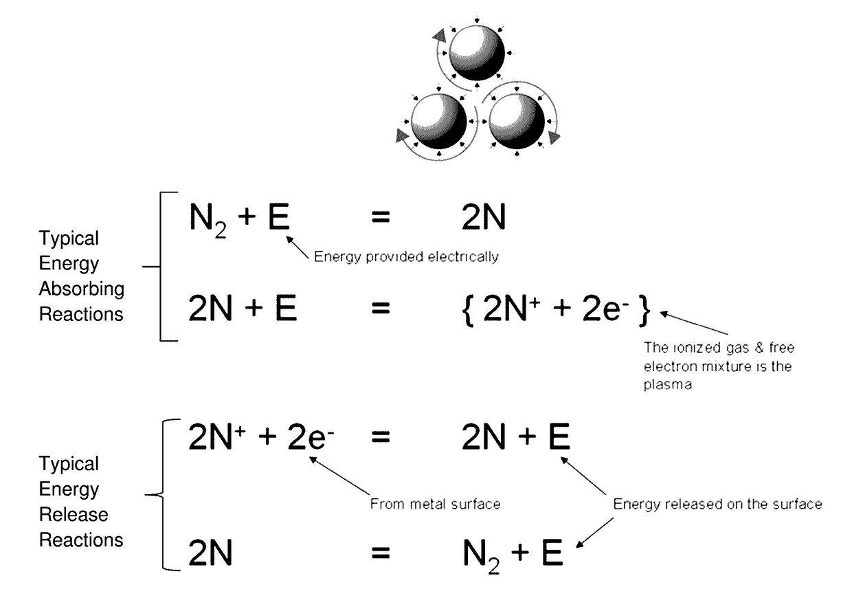
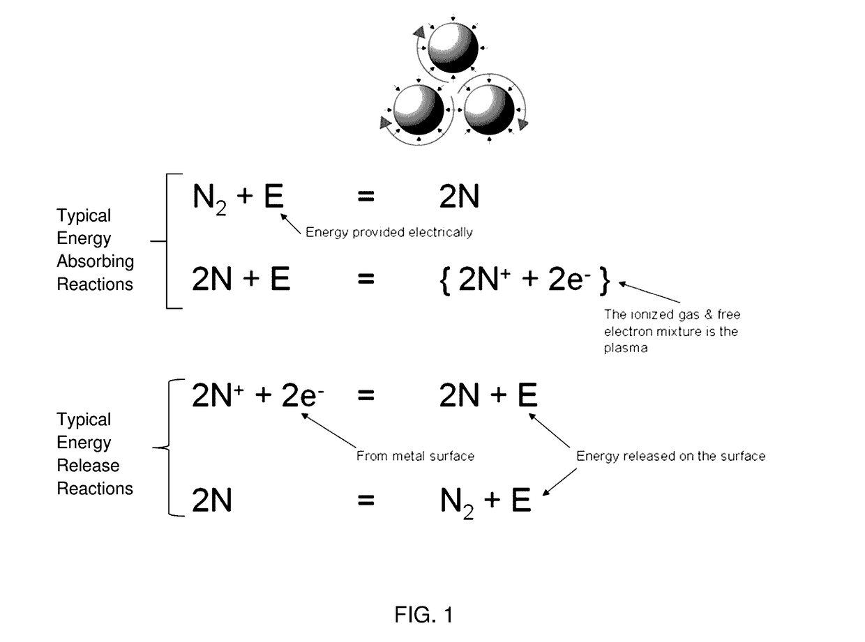
[0030]In an embodiment of the method, a coating, slurry, braze or other material is applied to the surface of an object. The substrate and the applied medium are then wrapped with a tape or foil. The tape or foil may be composed in part, or in total, of carbon or carbon material. A film of powder may be used as or in place of the foil. The substrate, applied material and wrapping are subjected to thermal plasma. The wrapping acts to attract the plasma or specific parts of the plasma in a manner that leads to rapid heat-up of the wrapped areas. The surface treatment is thus performed in a more efficient manner as compared to currently used processes that require far greater time and energy.

[0031]The method and apparatus of the method and the compositions of the foil and treatable combinations are special and involve selective ion electron combinations, particularly ones that change with temperatures. Activity increases above 1100° C. Copper brazing, hardfacing and de-burring become p...


PUM

PropertyMeasurementUnit
temperatureaaaaaaaaaa
diameteraaaaaaaaaa
Raaaaaaaaaaa

Abstract

Presented is a method for the surface treatment of objects utilizing thermal plasma, including cascade plasma, and a wrap, such as tape or foil, where the tape or foil attracts the specific part of the plasma which produces a heat necessary to produce the desired treatment. The specific surface treatment may include, but is not limited to, hard-facing, brazing, welding, other types of joining operations, glass bending or forming, glass texturing, coating and surface reconditioning.

Description

CROSS REFERENCE TO RELATED APPLICATIONS[0001]This patent application claims the benefit of provisional patents application Ser. No. 61 / 919,980, filed on Dec. 23, 2013 and application Ser. No. 61 / 925,719, filed Jan. 10, 2014 by the present applicants, the disclosures of which are incorporated by reference herein in their entirety.BACKGROUND[0002]Field[0003]This application presents a method for the surface treatment of objects utilizing thermal plasma, including cascade plasma, and a wrap, such as tape or foil, where the tape or foil attracts the specific part of the plasma which produces a heat and other properties necessary to produce the desired treatment. The specific surface treatment may include, but is not limited to, hard-facing, brazing, welding, other types of joining operations, glass bending, shaping or forming, glass texturing, coating and surface reconditioning.[0004]Prior Art[0005]Past and current heat treatment methods used for processes including hardening, curing, a...

Claims


Application Information

Patent Timeline
Patent Type & Authority Patents(United States)
IPC IPC(8): H05H1/24B23K1/20B23K35/02C03B29/00C03B29/02B23K1/005C03B23/00B23K1/00H01J37/32B23K101/00B23K103/00B23K103/04B23K103/08B23K103/12B23K103/14B23K103/18B23K103/20
CPCC03B23/0066B23K1/0018B23K1/0056B23K1/20B23K35/0244C03B29/00C03B29/025H01J37/3233B23K2201/001B23K2203/04B23K2203/08B23K2203/12B23K2203/14B23K2203/18B23K2203/20B23K2203/26B23K2203/52B23K2203/54B23K2203/56B23K2101/001B23K2103/04B23K2103/08B23K2103/12B23K2103/14B23K2103/18B23K2103/20B23K2103/26B23K2103/52B23K2103/54B23K2103/56
Inventor SEKHAR, JAINAGESHCONNELLY, MICHAEL
Owner MHI HEALTH DEVICES
Why Eureka
Try Eureka