Method for manufacturing eye-protecting liquid crystal display device

Active Publication Date: 2017-06-06
WUHAN CHINA STAR OPTOELECTRONICS TECH CO LTD
View PDF4 Cites 11 Cited by
  • Summary
  • Abstract
  • Description
  • Claims
  • Application Information

AI Technical Summary

Benefits of technology

[0009]An object of the present invention is to provide a method for manufacturing an eye-protecting liquid crystal display device, which converts ultraviolet light and short-wavelength blue light having a wavelength less than 400 nm, which could damage human eyes, into long-wavelength visible bl

Problems solved by technology

However, such blue light resistant protection film also lowers down display brightness of the liquid crystal di

Method used


Image

  • Method for manufacturing eye-protecting liquid crystal display device
  • Method for manufacturing eye-protecting liquid crystal display device
  • Method for manufacturing eye-protecting liquid crystal display device

Examples


Embodiment Construction

[0044]To further expound the technical solution adopted in the present invention and the advantages thereof, a detailed description is given to a preferred embodiment of the present invention with reference to the attached drawings.

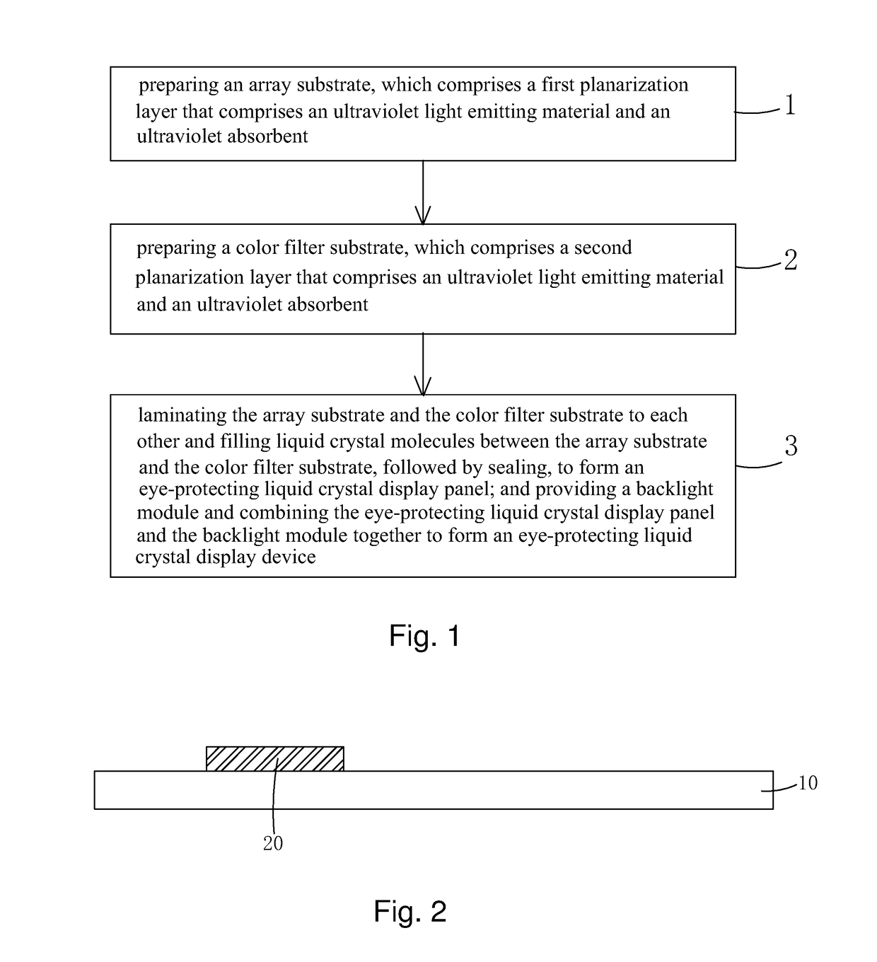
[0045]Referring to FIG. 1, the present invention provides a method for manufacturing an eye-protecting liquid crystal display device, which comprises the following steps:

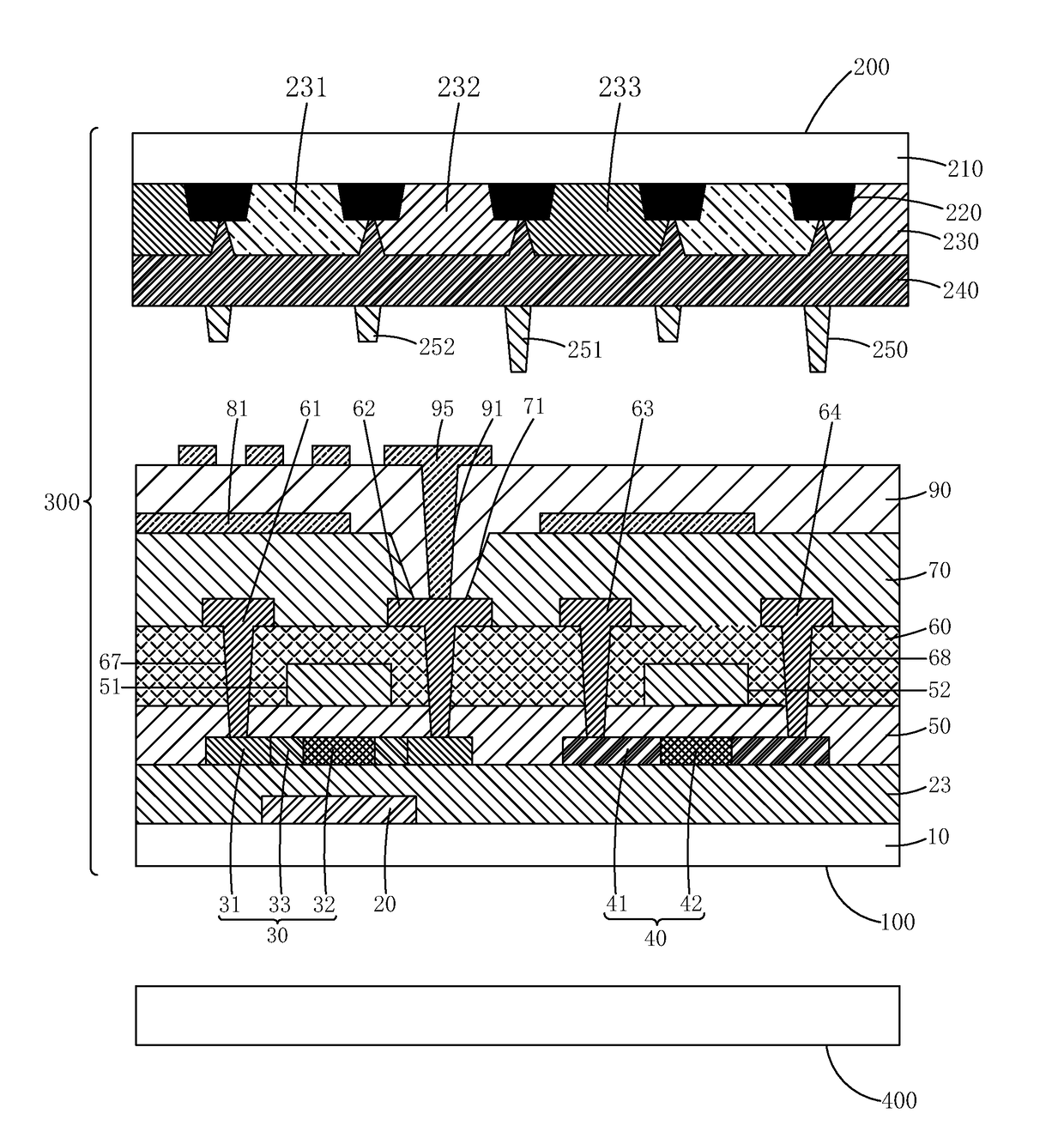
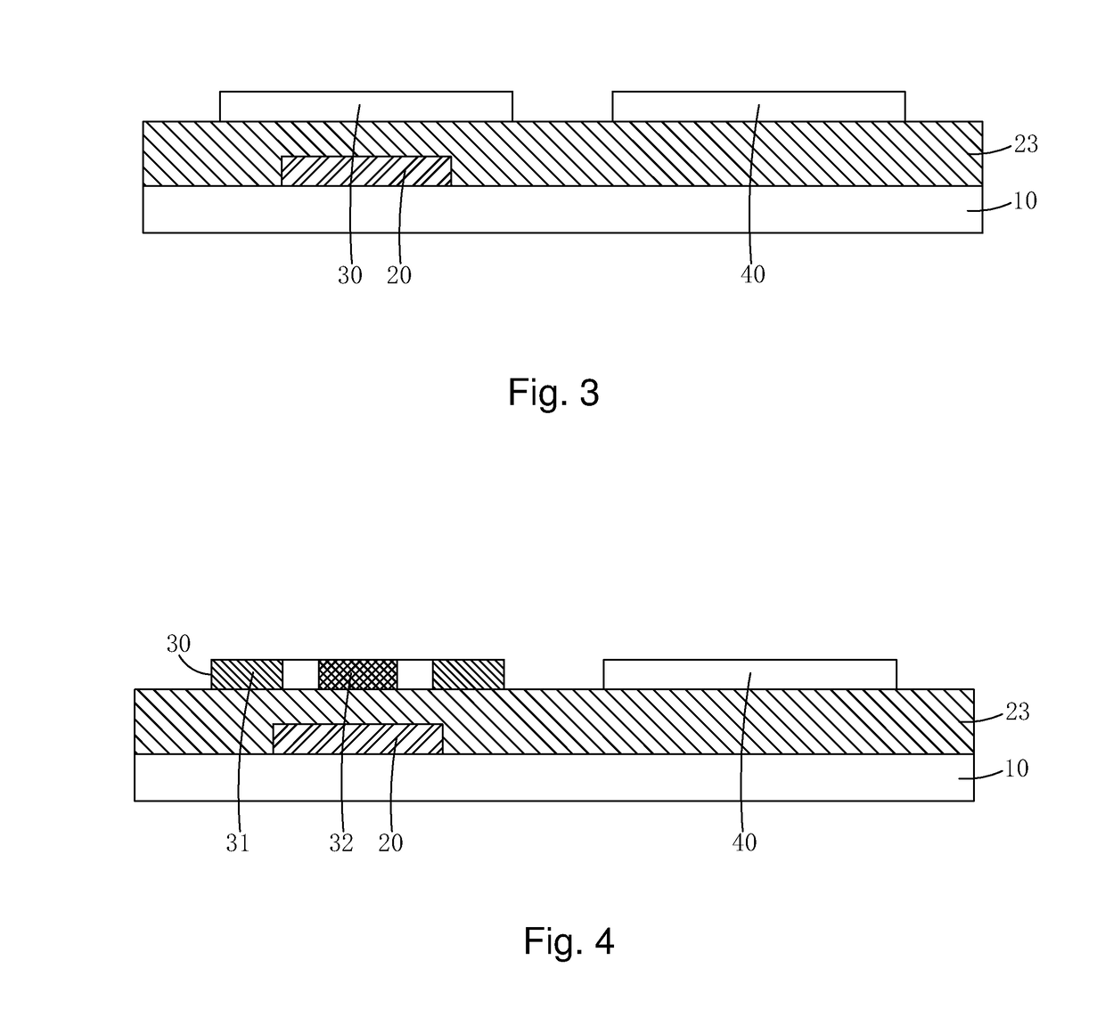
[0046]Step 1: referring to FIGS. 2-10, preparing an array substrate 100, wherein the array substrate 100 comprises a first backing plate 10; a light-shielding layer 20 located on the first backing plate 10; a buffer layer 23 located on the light-shielding layer 20 and the plate 10; a first poly-silicon section 30 and a second poly-silicon section 40 located on the buffer layer 23; a gate insulation layer 50 located on the first poly-silicon section 30, the second poly-silicon section 40, and the buffer layer 23; a first gate electrode 51 and a second gate electrode 52 located on the gate ...


PUM


Abstract

A method for manufacturing an eye-protecting liquid crystal display device is disclosed, in which an ultraviolet light emitting material and a ultraviolet absorbent are added in a first planarization layer of an array substrate and a second planarization layer of a color filter substrate. The ultraviolet absorbent absorbs short-wavelength blue light having a wavelength less than 400 nm and ultraviolet light emitting from a backlight module. The short-wavelength blue light and the ultraviolet light so absorbed excite the ultraviolet light emitting material to give off long-wavelength visible blue light having a wavelength greater than 400 nm. The first and second planarization layers are thus useful in converting ultraviolet light and short-wavelength blue light having a wavelength less than 400 nm, which could damage human eyes, into long-wavelength visible blue light having a wavelength greater than 400 nm that does not damage human eyes.

Description

BACKGROUND OF THE INVENTION[0001]1. Field of the Invention[0002]The present invention relates to the field of display technology, and in particular to a method for manufacturing an eye-protecting liquid crystal display device.[0003]2. The Related Arts[0004]With the progress of the display technology, flat panel display devices, such as liquid crystal displays (LCDs), due to various advantages, such as high image quality, low power consumption, thin device body, and wide range of applications, have been widely used in all sorts of consumer electronic products, including mobile phones, televisions, personal digital assistants (PDAs), digital cameras, notebook computers, and desktop computers, making them the main stream of display devices.[0005]Most of the liquid crystal display devices that are currently available in the market are backlighting LCDs, which comprise a liquid crystal display panel and a backlight module. The working principle of the liquid crystal display panel is that...

Claims


Application Information

Patent Timeline
IPC IPC(8): H01L33/00G02F1/1341G02F1/1335H01L27/12G02F1/1339G02F1/1333G02F1/1368H01L29/66G02F1/1362
CPCG02F1/133621H01L27/1248H01L27/1222G02F1/136209H01L27/127H01L29/66757G02F1/1368G02F1/133345G02F1/133516G02F1/133512G02F1/13394G02F1/1341G02F2001/13685G02F2001/133357G02F2202/02G02F2202/36G02F2203/055G02F2001/133614G02F2201/086G02F1/133514G02F1/134363H01L29/78621H01L29/78633G02F2203/05G02F1/133562G02F1/134372G02F1/13685G02F1/133357G02F1/133614
Inventor TANG, GUOQIANG
Owner WUHAN CHINA STAR OPTOELECTRONICS TECH CO LTD
Why Eureka
Try Eureka